Piezo Bender
Piezoelectric bimorph beam of rectangular cross-section
Libraries:
Simscape /
Electrical /
Electromechanical /
Mechatronic Actuators
Description
The Piezo Bender block models a piezoelectric bimorph beam of rectangular cross-section.
A piezo bender is a piezoelectric device that bends when you apply an electrical potential between its plates. Conversely, when a piezo bender bends, it generates an electrical potential.
A piezo bender comprises different rectangular layers of piezoelectric material with a polarization perpendicular to the stack. This polarization is alternated in each layer.
Equations
This figure shows the Cartesian reference frame
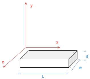
where:
L is the beam length.
w is the beam width.
d is the beam thickness.
These are the constitutive equations for a piezoelectric material in the stress-charge formulation,
| (1) |
| (2) |
where:
T is the stress field.
[c] is the compliance tensor.
S is the strain field.
[e] is the piezo stress coefficient tensor.
E is the electric field.
D is the electric displacement field.
[ϵS] is the permittivity tensor at constant or zero strain.
To model the flexibility, the block uses the Euler-Bernoulli finite-element beam equations. The translation and rotation of each beam cross-section in function of the x-axis determine the beam kinematics.
This block considers only the forces applied in the y direction and the piezoelectric material is polarized to bend only in the x-y plane. For this reason, to describe the kinematics, you only need to specify the vertical displacement in the y direction of the center of gravity of each cross-section, y(x), and the rotation around the z-axis of each cross-section, φz(x).
From the previous assumptions, the strain field in an Euler-Bernoulli beam subject to bending is equal to:
| (3) |
Because the electric field is constant between the positive and negative plates, , the block substitutes equation 3 into equation 1:
In this equation, E = c11 is the Young modulus of the material and e31 is the (3,1) piezoelectric stress-charge coupling coefficient, .
This equation defines the bending moment from the stress field:
Because the polarization of the material for is the opposite than the polarization for , the (3,1) piezoelectric stress-charge coupling coefficient changes sign and the bending moment is defined by
where is the second moment of area of the rectangular cross-section.
In this equation, the first term is the classical equation of a beam subject to bending, and the second term is the electromechanical coupling due to the presence of a voltage across the piezoelectric material. This voltage produces a uniform electrical bending moment loaded along the beam.
The block then substitutes equation 3 into equation 2:
The electric charge inside a volume is equal to the Gauss integral of the electric displacement:
Then, this equation defines the charge accumulated between the two sections of the beam due to the piezoelectric effect:
Finally, from the mechanical perspective, you can model a piezo bender as an Euler-Bernoulli beam loaded with a uniform torque that is proportional to the voltage:
From the electrical perspective, you can model a piezo bender as a capacitor with a charge source proportional to the bending angle:
Finite Element Formulation
To discretize and solve the Euler-Bernoulli equations with the piezoelectric coupling, the Piezo Bender block uses a Finite Element method.
The block discretizes the piezo bender beam into a number of slices in the length direction with the same width, w, and thickness, d. The length of each element is equal to the total length of the beam divided by the number of elements, .
This stiffness matrix of a finite element of an Euler-Bernoulli beam defines the relationship between the vertical displacement and rotational angle of each end of the beam element, and the corresponding forces and moments due to the beam elasticity:
Then, to obtain the equations for a piezo bender beam element, add the coupling terms and the mass matrix for the inertia:
Finally, this is the equation for a piezo bender beam element with damping:
where:
l is the element length.
w is the element width.
d is the element thickness.
is the second moment of area.
E is the Young modulus.
m = ρlwd is the element mass, where ρ is the mass density.
e31 is the (3,1) piezoelectric stress-charge coupling coefficient, .
ε is the electrical permittivity.
is the damping matrix.
bm is the Rayleigh damping coefficient proportional to mass.
bk is the Rayleigh damping coefficient proportional to stiffness.
is the stiffness finite element matrix.
is the mass matrix.
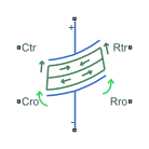
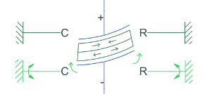
yC is the deflection along the y-axis of the left-end of the element.
yR is the deflection along the y-axis of the right-end of the element.
φC is the rotation around the z-axis of the left-end of the element.
φR is the rotation around the z-axis of the right-end of the element.
FC is the force along the y-axis of the left-end of the element.
FR is the force along the y-axis of the right-end of the element.
TC is the torque in the z-axis of the left-end of the element.
TR is the torque in the z-axis of the right-end of the element.
v is the voltage across the top and bottom electrodes.
q is the accumulated charge between the electrodes and the piezoelectric material.
Datasheet Parameterization
A datasheet of a piezo bender usually provides this data:
Dimensions (l, w, d)
Mass, m
Rated voltage, vrated
Free deflection at rated voltage, yfree
Blocking force at rated voltage, Fblock
Capacitance, Cpiezo
First resonant frequency, f1
It is possible to calculate the fundamental material parameters of a piezo bender by using the datasheet parameters.
First, the block solves the voltage-force deflection relationships from the steady-state equations with no torque applied and clamped-free configuration:
These equations define the relationship between the tip deflection, voltage and tip force:
The block computes the capacitance by assuming zero applied force:
Finally, this equation shows the relationship between density and mass:
Once you have defined all the relationships between the fundamental and datasheet parameters, you can calculate the fundamental parameters with these equations:
Then substitute these equations in the constitutive equations:
You can calculate the first resonance frequency of a clamped-free beam of uniform cross section by using this equation:
The block then parameterizes the dynamics directly by specifying the desired natural frequency.
Boundary Conditions
Beams have different boundary conditions at their left and right ends:
Free — Both the displacement and rotation are equal to any value.
Simply supported — The displacement is equal to
0.Clamped — Both the displacement and rotation are equal to
0.
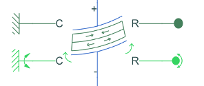
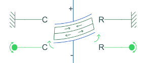
This table shows the possible boundary configurations for a piezo bender beam.
| Configuration | Model |
|---|---|
| Clamped-free |
|
| Supported-supported |
|
| Clamped-clamped |
|
Examples

Piezo Bender Energy Harvester
Model a device that harvests energy from a vibrating object by using a piezo bender. The device uses this energy to charge a battery and power a load. These devices are common in low-power applications that require energy autonomy, such as wearable devices or sensors in vehicles.
Ports
Conserving
Parameters
References
[1] Tadmor, E. B., and G. Kosa. "Electromechanical Coupling Correction for Piezoelectric Layered Beams." Journal of Microelectromechanical Systems, vol. 12, no. 6, Dec. 2003, pp. 899–906. DOI.org (Crossref), doi:10.1109/JMEMS.2003.820286.
[2] Benjeddou A, Trindade MA, Ohayon R. "A Unified Beam Finite Element Model for Extension and Shear Piezoelectric Actuation Mechanisms." Journal of Intelligent Material Systems and Structures. 1997;8(12):1012-1025. doi:10.1177/1045389X9700801202
[3] Gavin, Henri P. "Beam Element Stiffness Matrices." CEE 421L. Matrix Structural Analysis. Duke University, 2014.
Extended Capabilities
Version History
Introduced in R2021a