Linear Transformer
(To be removed) Implement two- or three-winding linear transformer
The Specialized Power Systems library will be removed in R2026a. Use the Simscape™ Electrical™ blocks and functions instead. For more information on updating your models, see Upgrade Specialized Power Systems Models to use Simscape Electrical Blocks.
Libraries:
Simscape /
Electrical /
Specialized Power Systems /
Power Grid Elements
Description
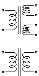
The Linear Transformer block model shown consists of three coupled windings wound on the same core.

The model takes into account the winding resistances (R1 R2 R3) and the leakage inductances (L1 L2 L3), as well as the magnetizing characteristics of the core, which is modeled by a linear (Rm Lm) branch.
The Per Unit Conversion
In order to comply with industry, the block allows you to specify the resistance and inductance of the windings in per unit (pu). The values are based on the transformer rated power Pn in VA, nominal frequency fn in Hz, and nominal voltage Vn in Vrms, of the corresponding winding. For each winding, the per unit resistance and inductance are defined as
The base impedance, base resistance, base reactance, and base inductance used for each winding are
For the magnetization resistance Rm and inductance Lm, the pu values are based on the transformer rated power and on the nominal voltage of winding 1.
For example, the default parameters of winding 1 specified in the dialog box section give the following bases:
Suppose that the winding 1 parameters are R1 = 4.32 Ω and L1 = 0.4586 H; enter the corresponding values in the dialog box:
To specify a magnetizing current of 0.2% (resistive and inductive) based on nominal current, you must enter per unit values of 1/0.002 = 500 pu for the resistance and the inductance of the magnetizing branch. Using the base values calculated previously, these per unit values correspond to Rm = 1.08e6 ohms and Lm = 2866 H.
Modeling an Ideal Transformer
To implement an ideal transformer model, set the winding resistances and
inductances to 0, and the magnetization resistance and inductance (Rm Lm) to
inf.
Limitations
Windings can be left floating (that is, not connected to the rest of the circuit). However, an internal resistor is automatically added between the floating winding and the main circuit. This internal connection does not affect voltage and current measurements.
Due to limitations inherent to graph theory and its application to electric network theory as implemented in Simscape Electrical Specialized Power Systems, the following topologies are unsolvable:
Loops containing only ideal transformer secondary windings (for example, delta-connected ideal secondary windings of three-phase transformer). To solve this topology issue, you can add a small impedance in series with the loop.
Loops containing only ideal transformer secondary windings and ideal voltage sources. To solve this topology issue, you can add a small impedance in series with the loop.
Loops containing only ideal transformer secondary windings and capacitors. To solve this topology issue, you can add a small impedance in series with the loop.
All topologies where an ideal transformer primary has at least one of its nodes that is connected to elements consisting only of ideal transformer primary windings or current sources (for example, wye-connected three-phase primary windings with floating common point). To resolve this circuit topology, you connect a small resistance to problematic node.
Ports
Conserving
Parameters
Extended Capabilities
Version History
Introduced before R2006a