Transformer Hysteresis Design Tool
View and edit hysteresis characteristic for saturable core of Saturable Transformer blocks
Description
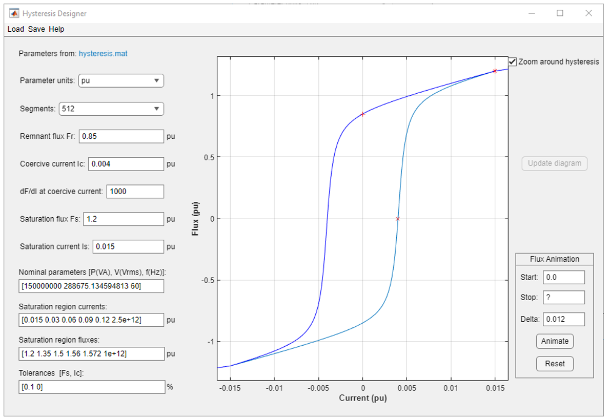
The Hysteresis Designer app allows you to view and edit a hysteresis characteristic for the saturable core of the Multi-Winding Transformer, Saturable Transformer, Three-Phase Transformer (Two Windings), and Three-Phase Transformer (Three Windings) blocks. The hysteresis characteristic includes the saturation region located at the limits of the hysteresis loop.
A default hysteresis characteristic displays when you open the app, but you can build as many hysteresis characteristics as you want and save them in different MAT-files. You can use the same characteristic for all your transformer blocks, or you can use different characteristics for each transformer block in the circuit. In the mask of a transformer block, select Simulate hysteresis and specify a MAT-file to use.
The Hysteresis Designer app includes a flux animation tool that can visualize how by Simscape™ Electrical™ Specialized Power Systems software performs the simulation of the hysteresis. This is an optional tool that is not necessary for the model parameterization. The app calculates the initial trajectory according to the defined hysteresis characteristic. The tool assumes that the last reversal point before starting flux is located on the major loop. The operating point travels until the defined stop flux.
Open the Transformer Hysteresis Design Tool App
MATLAB® command prompt: Enter
power_hysteresis
In the Powergui block, click Hysteresis Designer
Parameters
Hysteresis ParametersParameter units
— App parameter units
pu
(default) | SI
Convert the fluxes and currents that define the hysteresis characteristic from
SI
to pu
or from
pu
to SI
.
Segments
— Number of linear segments
512
(default) | 32
| 64
| 128
| 256
Number of linear segments used to define the right side of the hysteresis loop. The left side of the loop is the symmetric image of the right side.
Remnant flux FR
— Remnant flux
0.85 (default) | positive scalar
Remnant flux point of the hysteresis characteristic (flux at zero current). The remnant flux point is identified by a + mark in the plot.
Coercive current IC
— Coercive current
0.004 (default) | positive scalar
Coercive current point of the hysteresis characteristic.
dF/dI at coercive current
— Flux slope at coercive current
1000 (default) | positive scalar
Slope of the flux at the coercive current point (current at zero flux).
Saturation flux Fs
— Saturation flux
1.2 (default) | positive scalar
Saturation flux point where the hysteresis loop becomes a single-valued saturation curve. The saturation flux point is identified by a * mark in the plot.
Saturation current Is
— Saturation current
0.015 (default) | positive scalar
Saturation current point where the hysteresis loop becomes a single-valued saturation curve. The saturation region is defined by the Saturation region currents parameter.
Nominal parameters [ P(VA), V(Vrms), f(Hz) ]
— Transformer nominal parameters
[150e6, 500e3/sqrt(3), 60] (default) | vector of 3
Nominal parameters (nominal power in VA, nominal voltage of winding 1 in volts RMS, and nominal frequency in Hz) used in the conversion of the hysteresis parameters.
Saturation region currents
— Saturation current
[0.015 0.03 0.06 0.09 0.12 2.5e+12] (default) | vector
Vector of current values that define the saturation characteristic. The number of specified points must be the same as the Saturation region fluxes parameter. You need to specify only the positive part of the characteristic.
Saturation region fluxes
— Saturation current
[1.2 1.35 1.5 1.56 1.572 1e+12] (default) | positive scalar
Vector of flux values that define the saturation characteristic. The number of specified points must be the same as for the Saturation region currents parameter. You need to specify only the positive part of the characteristic.
Tolerances [Tol_F, Tol_I]
— Saturation current
0.015 (default) | positive scalar
This parameter is mainly used to minimize the generation of superfluous, very small internal loops or new trajectories because they have little effect and they consume computer memory space. The model can memorize up to 50 embedded minor loops at any time.
The TOL_F parameter is the tolerance value used to detect whether, after a flux reversal, the operating point remains on the same minor loop or a new embedded loop is created. The smaller the value, the lesser the effect on the normal trajectory behavior. The bigger the value, the lesser the generated number of embedded minor loops.
Finally, when the distance between the I coordinate of the actual point of reversal and the penultimate one is less than TOL_I, then evolution within these two points follows a line segment instead of a loop.
Zoom around hysteresis
— Saturation current
on (default) | off
Select to zoom the plot around the hysteresis curve.
Start
— Starting flux
0.0 (default) | scalar
Starting flux.
Stop
— Ending flux
? (default) | scalar
Flux at which the flux animation stops.
Delta
— Flux delta
1,78e-08 (default) | positive scalar
Flux increment, in pu or SI, that is used to go from start flux to stop flux.
Update diagram
— Update hysteresis diagram
Update the hysteresis diagram after you changed hysteresis parameters.
Animate
— Animate flux animation
Start the flux animation tool.
Reset
— Reset flux animation
Reset the flux animation tool.
Load
— Load hysteresis parameters
Opens a browser window where you can select your own cable data. Select the desired MAT-file.
Save
— Save hysteresis parameters
Saves your cable data by generating a MAT-file that contains the GUI information and the cable data.
Help
— App documentation
Open the documentation page of the app.
Version History
Introduced in R2021b