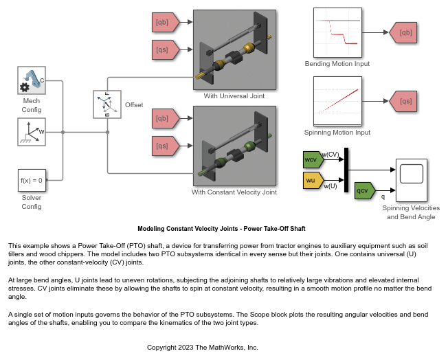
Modeling Constant Velocity Joints - Power Take-Off Shaft
This example shows a Power Take-Off (PTO) shaft, a device for transferring power from tractor engines to auxiliary equipment such as soil tillers and wood chippers. The model includes two PTO subsystems identical in every sense but their joints. One contains universal (U) joints, the other constant-velocity (CV) joints.
At large bend angles, U joints lead to uneven rotations, subjecting the adjoining shafts to relatively large vibrations and elevated internal stresses. CV joints eliminate these by allowing the shafts to spin at constant velocity, resulting in a smooth motion profile no matter the bend angle.
A single set of motion inputs governs the behavior of the PTO subsystems. The Scope block plots the resulting angular velocities and bend angles of the shafts, enabling you to compare the kinematics of the two joint types.