Model Gear Backlash by Using Joint Limits
R2026bIn this example, you learn how to model backlash in a gear assembly using a Revolute Joint block with upper and lower joint limits. You can use the Revolute Joint block to add an additional degree of freedom to the follower gear, which allows relative motion between the gears when the teeth are not in contact. The amount of play between the gears is constrained within the joint limits you specify.
Modeling gear backlash is important because it captures the contact-separation-impact cycle of gear teeth that occurs during starts, stops, and torque reversals. This behavior generates sharp torque spikes when the teeth re-engage, a temporary loss of torque transmission in the free-motion region, and other nonlinear dynamics that influence overall system performance. In this example, you also observe the effect of backlash on gear velocity and gear tooth contact force at the pitch circle.
Open the Model
Open GearBacklash_Starter.
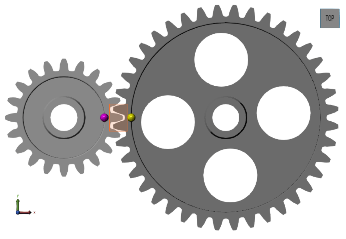
open_system("GearBacklash_Starter");The model represents a gear assembly between two external spur gears that are constrained with a Common Gear Constraint block. A PS Sine Wave block with an amplitude of 5e-4 N*m represents the torque applied to the base gear. The geometry defining the gear bodies corresponds to 1 mm of normal backlash between the gears. Run the model.
noBacklashSimOut = sim("GearBacklash_Starter");During simulation, the Multibody Explorer opens and displays an animation of the gear bodies. Although a backlash gap is specified in the gear geometry, the Common Gear Constraint block keeps the gears in mesh, so there is no separation and re-engagement of gear teeth during simulation. Observe that the gear teeth remain meshed but do not actually touch because the starter model does not include backlash.
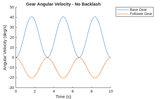
Because the gears remain in mesh during simulation, the angular velocities of both gears respond smoothly to the sinusoidal torque input. To see the angular velocity of the gears during simulation, create a plot of the velocity.
figure
hold on
plot(getElement(noBacklashSimOut.logsout,"w_base_starter").Values)
plot(getElement(noBacklashSimOut.logsout,"w_follower_starter").Values)
xlabel("Time (s)")
ylabel("Angular Velocity (deg/s)")
legend("Base Gear","Follower Gear","Location","northeastoutside")
title("Gear Angular Velocity - No Backlash")
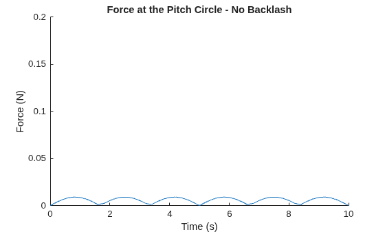
Also notice that the model does not produce gear tooth contact force spikes at the pitch circle, since the Common Gear Constraint block prevents tooth separation and re-engagement. To examine the gear contact force during simulation, create a plot of the interface force at the pitch circle.
figure
hold on
plot(getElement(noBacklashSimOut.logsout,"F_starter").Values)
ylim([0 0.2])
xlabel("Time (s)")
ylabel("Force (N)")
title("Force at the Pitch Circle - No Backlash")
Add Rotational Play to Model Gear Backlash
Add a Revolute Joint block between the Conn2 Connector block from the Follower Gear Geometry subsystem and the F port of the Common Gear Constraint block. Name this block Backlash.
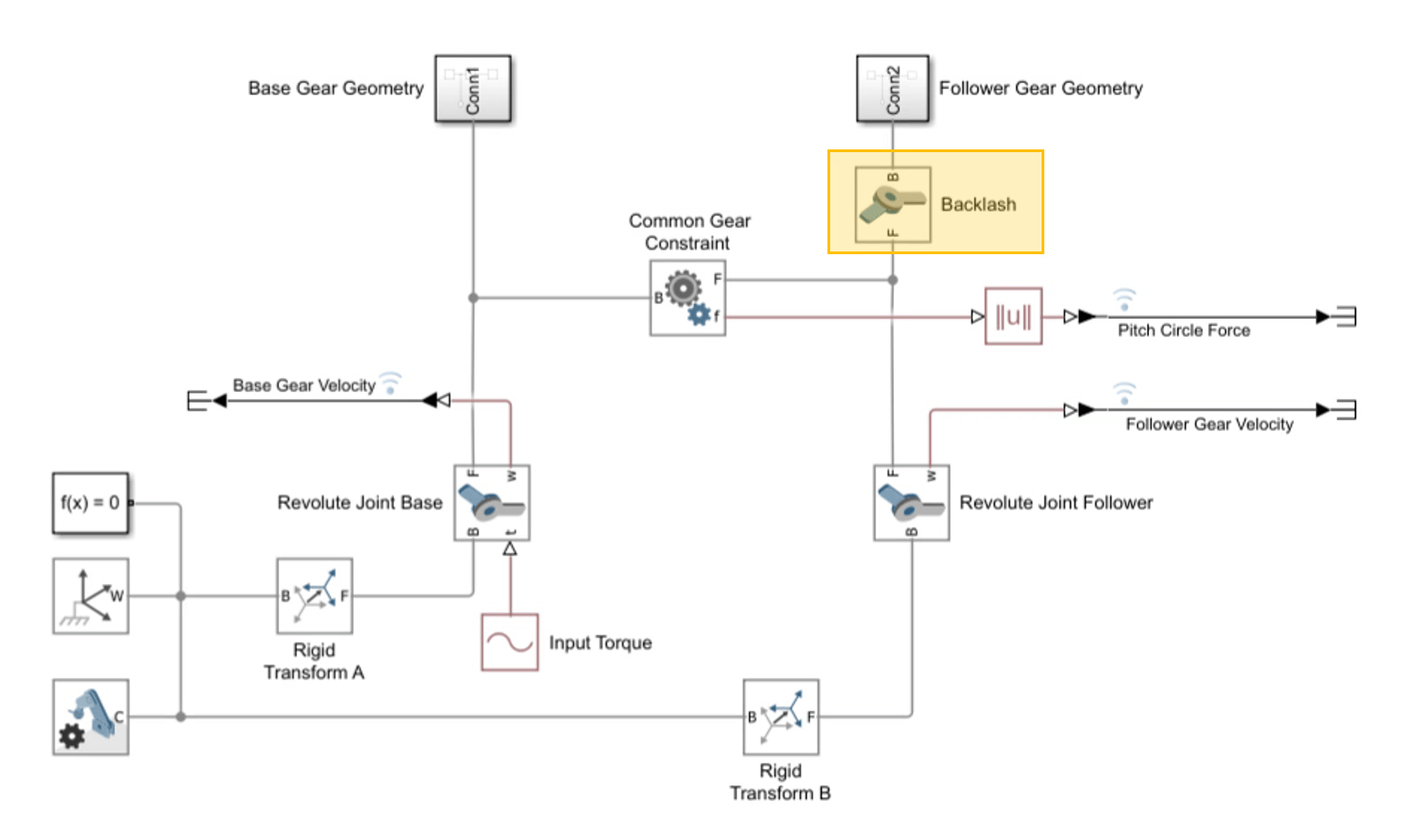
Open the Backlash block. In the Z Revolute Primitive (RZ) > Limits section, enable Specify Lower Limit and Specify Upper Limit. To model the backlash, you calculate the value for the Specify Lower Limit > Bound and Specify Upper Limit > Bound parameters by calculating the joint limits on the follower gear.
1. Measure the distance between the gear teeth along the pitch circle of the follower gear when the gears are at one end of the backlash gap. In this example, the linear backlash is 1.00 mm.
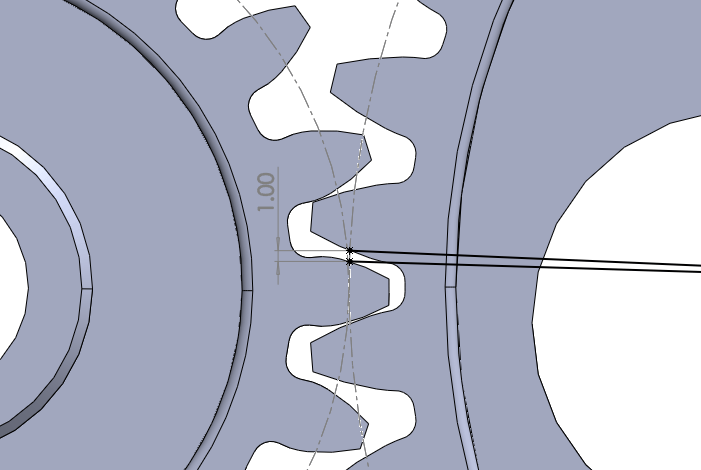
2. Convert the linear backlash to angular backlash by using the equation
,
where:
is the backlash angle in degrees
is the linear backlash measured along the pitch circle
is the follower gear pitch circle radius
3. For this example, = 1 mm and = 80 mm, which yields a total angular backlash of 0.72°. Split the total angular backlash evenly to define symmetric upper and lower joint limits of 0.36°.
4. In the Backlash block, set the Specify Lower Limit > Bound parameter to -0.36 deg and the Specify Upper Limit > Bound parameter to +0.36 deg. These limits represent the angular play introduced by the 1 mm backlash in the tooth profile geometry, translated into equivalent rotational clearance between the base and follower gears.
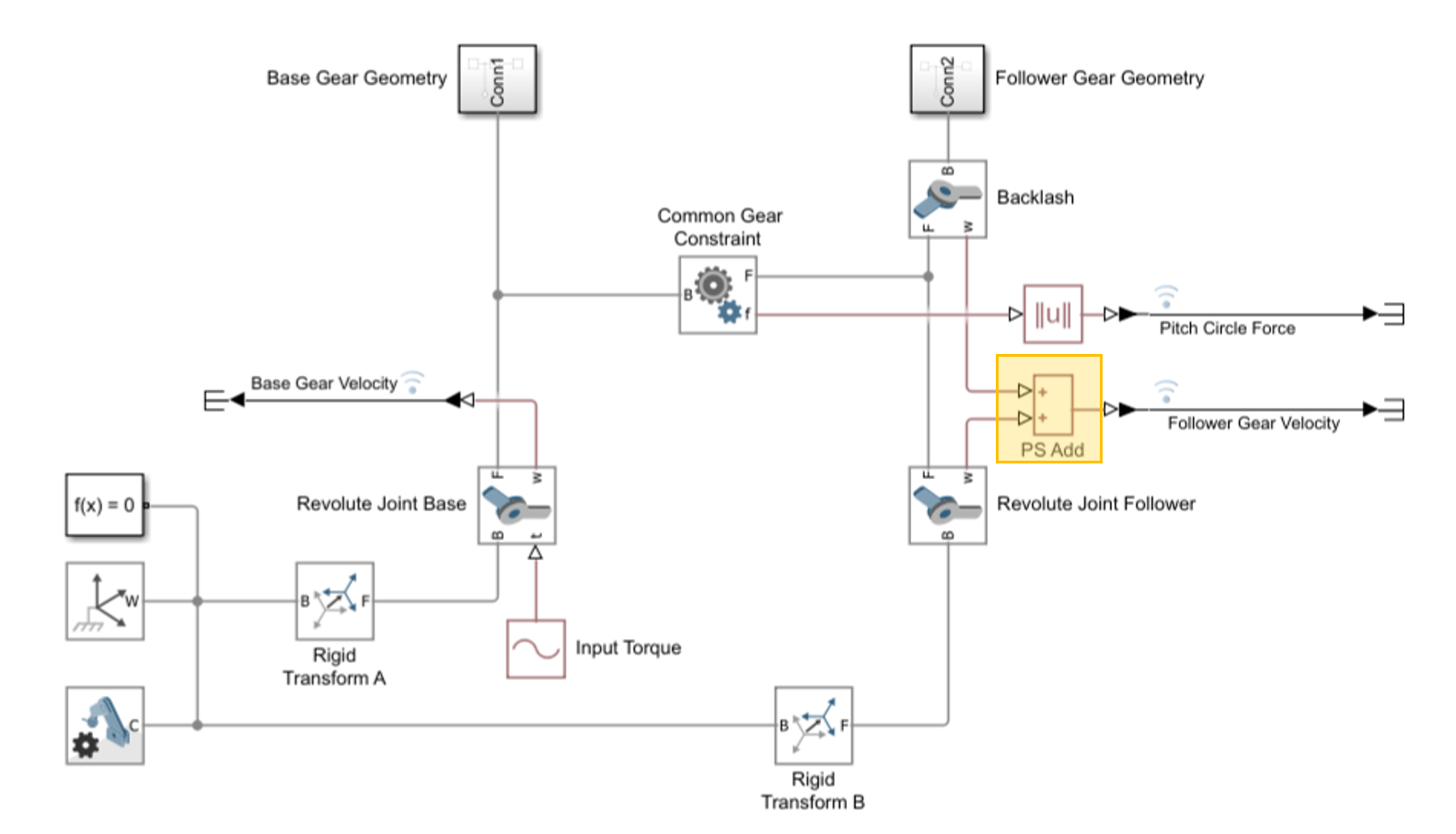
To correctly measure the follower gear angular velocity, you must now account for the motion of both revolute joints. Enable velocity sensing on the Backlash block by opening the Z Revolute Primitive (Rz) > Sensing section and enabling Velocity. Use a PS Add block to sum the velocity signals from the two revolute joints.
Add a Dummy Mass to Resolve Degenerate Mass Error
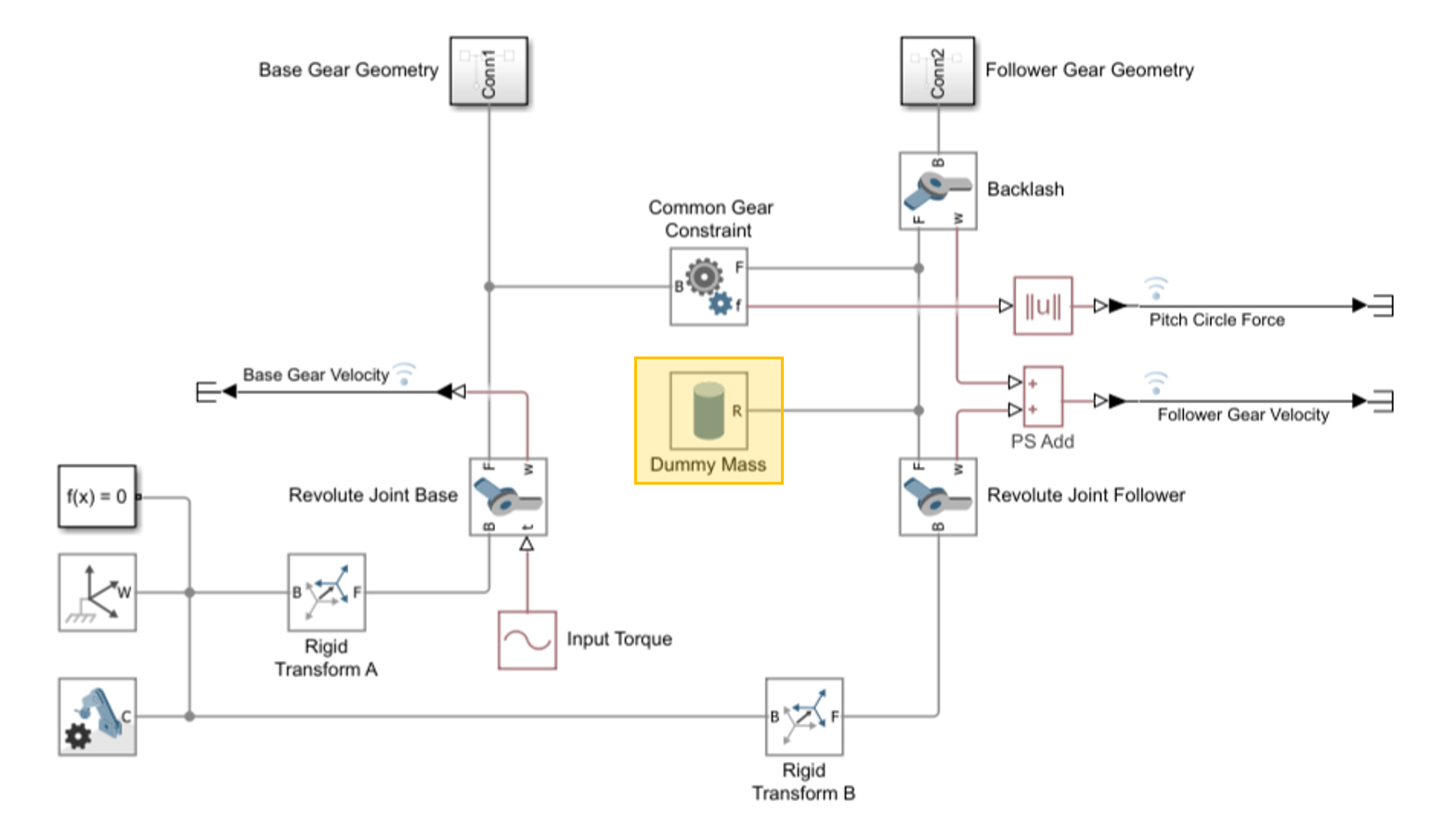
If you simulate the model now, Simulink returns a degenerate mass error. This error occurs when two Revolute Joint blocks are connected in series. To resolve this error, you insert a small amount of rotational inertia between the Revolute Joint blocks. Use a mass that is to times smaller than the follower gear mass to provide a small amount of rotational inertia without meaningfully affecting the system dynamics.
Add a Cylindrical Solid block between the Backlash and Revolute Joint Follower blocks. Because the follower gear mass is defined by its geometry and density in this example, model the dummy mass using a Cylindrical Solid block with geometry similar to the follower gear and adjust the density accordingly. To do so, set:
Geometry > Radius to
8 cmGeometry > Length to
1 cmInertia > Type to
Calculate from geometryInertia > Based on > Density to
1 kg/m^3Graphic > Visual Properties > Opacity to
0.1Block Name >
Dummy Mass
The model now runs without error.
Simulate the Model
Open the model GearBacklash_Final. This model contains the changes from this example. Simulate the model.
open_system("GearBacklash_Final");
withBacklashSimOut = sim("GearBacklash_Final");
During simulation, the Multibody Explorer displays the gear behavior:
At simulation start, the gears are positioned at the center of the backlash gap.
The follower gear does not move until 0.27 seconds, when it reaches its joint limit and the gear teeth collide. The collision between gear teeth changes the velocity of both gears.
The gear teeth remain engaged until 1.8 seconds, when deceleration causes the gear teeth to lose contact and separate within the backlash gap.
At 2.0 seconds, the gear teeth collide again, which changes the velocity of both gears.
Both gears reach zero velocity at 3.3 seconds. At this point, the gears are positioned at one side of the backlash gap.
At 3.7 seconds, the gear teeth collide again. The pattern repeats for the remainder of the simulation time.
To examine how the addition of backlash affects gear velocity, plot the angular velocity of the updated model.
figure;
hold on;
plot(getElement(withBacklashSimOut.logsout,"w_base_final").Values)
plot(getElement(withBacklashSimOut.logsout,"w_follower_final").Values)
xlabel("Time (s)")
ylabel("Angular Velocity (deg/s)")
legend("Base Gear","Follower Gear","Location","northeastoutside")
title("Gear Angular Velocity with Backlash")
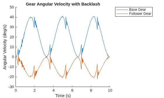
Notice that the gear velocity spikes every time there is a gear tooth collision. These collisions occur once during gear acceleration and once during gear deceleration.
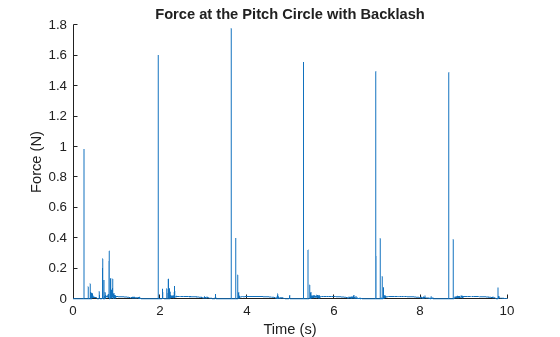
Every time the gear teeth collide, the contact force between gear teeth also spikes. To examine how backlash affects this force, plot the pitch circle contact force for updated model.
figure
hold on
plot(getElement(withBacklashSimOut.logsout,"F_final").Values)
xlabel("Time (s)")
ylabel("Force (N)")
title("Force at the Pitch Circle with Backlash")