Video Input
Libraries:
Simulink Desktop Real-Time
Description
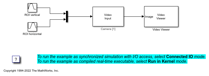
The Video Input block lets you get video data from system video devices. The camera device support includes support for video input from standard USB video class devices (webcams). The block also can output video frames status as ready or corrupted, and include the frame presentation timestamp. You can select the output format and region-of-interest (ROI).
The block gets the camera resolution from the configuration of the data acquisition board, for example a system camera that you install by using the block option to Install new board > Standard Devices > Camera.
The device configuration interface for the camera consists of camera ID, frame dimensions (width and height), and optional luminance channel toggle.
The camera ID is an integer number greater than or equal to one, specifying order of the accessed camera in the system. For example, the first, primary camera listed by the system has ID of 1. The camera ID default value is 1.
The frame width and height determine the required resolution of the video input. Maximum allowed resolution is FHD (1920x1080). The default dimensions are VGA (640x480).
The luminance channel toggle is a checkbox determining if the camera device should calculate luminance channel of the video, in addition to the RGB channels. Its default value is TRUE (checked).
You can test or accept the configuration by using Test and OK buttons. In case the camera configuration is invalid, the test or setting process fails and shows an error message. The camera configuration can fail for multiple reasons, for example absence of a camera with specified ID in the system, the specified resolution not being supported by the camera, or hardware failure.
