Run a Test Suite and Resolve Missing Model Coverage
This example shows how to run a test suite, collect coverage, and generate test cases to satisfy missing model coverage.
In this example, you perform requirements-based testing on the Simulink® model that implements an algorithm that calculates the vehicle target speed in the adaptive cruise control of an autonomous vehicle. Your tests must ensure that your development team implemented the algorithm according to the requirements.
In this example, a test suite contains several test cases linked to requirements. You use:
Requirements Toolbox™ to manage requirements in the Simulink environment
Simulink® Test™ to develop, manage, and execute simulation-based tests
Simulink® Coverage™ to measure test coverage for Simulink models and generated code
Simulink® Design Verifier™ to detect design errors, generate tests to achieve test coverage goals, and formally verify requirements using static analysis
Model coverage is a measure of how much of your design has been tested through simulation. Having full model coverage raises confidence that you have thoroughly tested the behavior of your model. Missing model coverage may be the result of dead logic, incomplete testing, unexpected functionality, or incomplete or missing requirements.
Open Test Suite in Test Manager
First, open the project.
prj = openProject("RequirementsBasedTestingProject");Open the test file in the Test Manager.
sltest.testmanager.clear
sltest.testmanager.load('CruiseControl_TestSuite.mldatx');
sltest.testmanager.view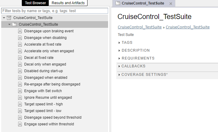
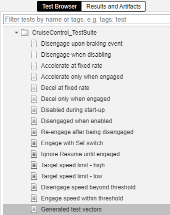
The test suite consists of many test cases, each of which tests a single requirement.
Enable Coverage Analysis
To enable model coverage in the Test Manager:
In the Test Browser pane, click the CruiseControl_TestSuite test suite.
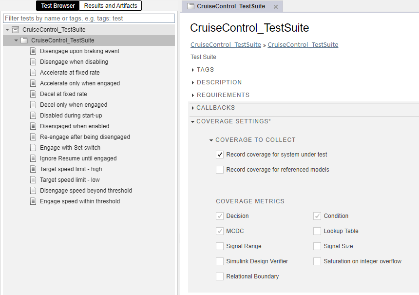
Open the Coverage Settings section.
In the Coverage to Collect section, select Record coverage for system under test.
In the Coverage Metrics section, Decision, Condition, and MCDC are selected. To learn more about these coverage metrics, see Types of Model Coverage.
Execute Test Suite
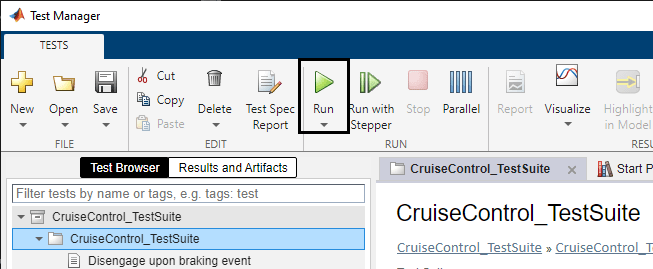
In the Test Browser pane, select the test suite CruiseControl_TestSuite, and click Run.
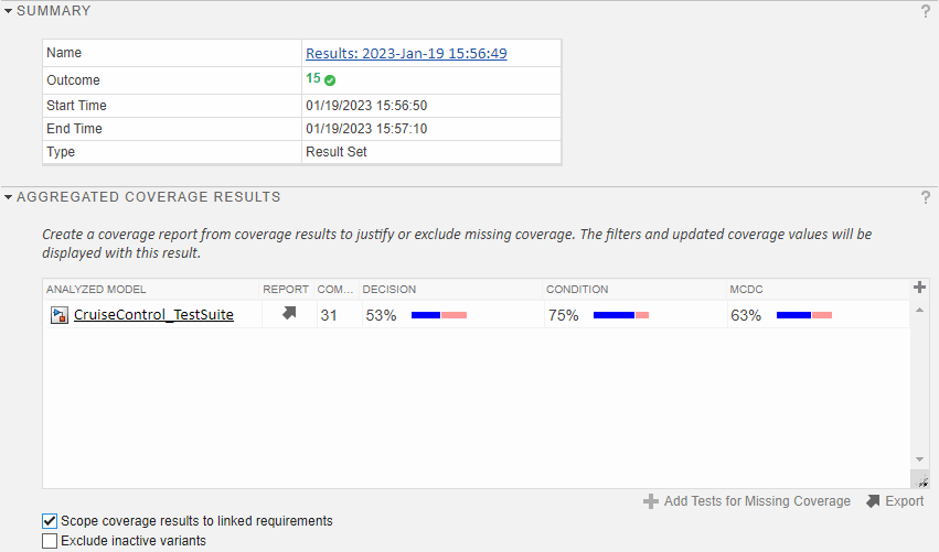
The Test Manager switches to the Results and Artifacts tab to show the test execution progress. This test suite has 15 test cases.
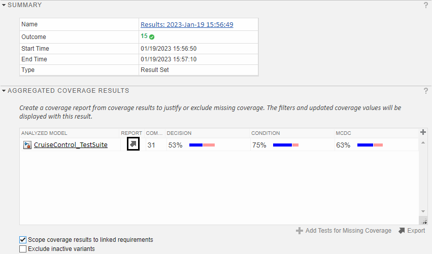
View Model Coverage Results
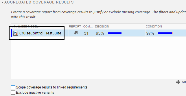
To view model coverage results, click the most recent test run in the Results and Artifacts tab, then expand Aggregated Coverage Results. Collecting model coverage for multiple tests of the same model and adding the results into a single coverage summary is called coverage aggregation because model coverage is collected for each test case and then aggregated across all test cases in the test suite.
The tests report almost full coverage. To confirm that the coverage received is based on the correct requirements, select Scope coverage results to linked requirements.

The tests now scope the coverage results based on requirements.
The coverage results decrease when you scope them to requirements. This decrease is due to incidental coverage, which occurs when a test case exercises a part of the model that is not associated with the requirement that the test case is meant to test. In requirements-scoped coverage, an objective is only fully covered if it is fully exercised by the test case linked to the requirement for that objective.
To investigate further, open the coverage results by clicking the report icon in Aggregated Coverage Results.
The coverage report displays the summary for the coverage results that are scoped to linked requirements. Missing coverage is colored red, and most of this missing coverage is due to incidental coverage, which you removed by scoping the results to linked requirements.

In the Summary section, click SF:ON.
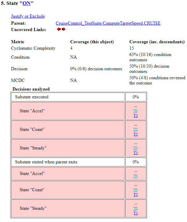
Most of the coverage objectives have an associated test case, even though they are not satisfied. In addition, there are no requirements links for the "ON" state. For an example of a fully covered coverage objective, look at the Transition from Junction #0 to Junction #1.
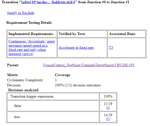
The Stateflow transition is fully exercised by test case T3, which is the test case associated with the parent requirement for the transition. In this case, the Stateflow transition has no incidental coverage.
Resolve Incidental Coverage
To resolve the incidental coverage for the "ON" state, look at the requirements to determine whether the project has a missing requirement or the "ON" state implements an existing requirement.
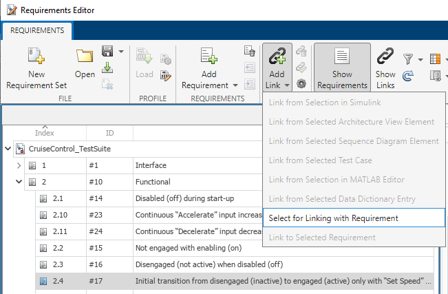
Open the requirements set in the Requirements Editor:
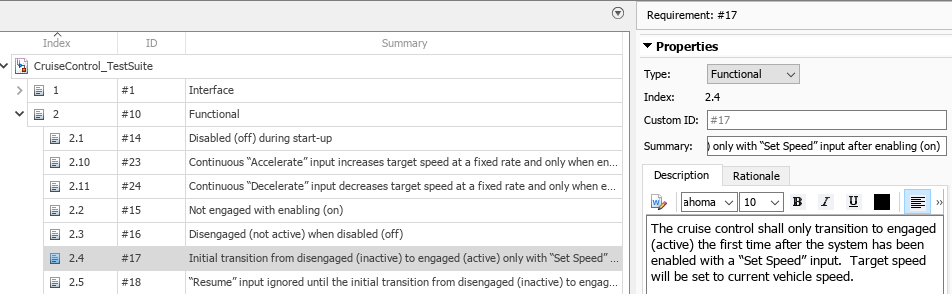
slreq.clear
reqSet = 'CruiseControl_TestSuite.slreqx';
slreq.open(reqSet);
rmi.navigate('linktype_rmi_slreq',reqSet,'17')
clear reqSet
Requirement 2.4 is the correct requirement to associate with this part of the design.
In the Requirements Editor, create a link from requirement 2.4 to the state by selecting the requirement and clicking Add Link > Select for Linking with Requirement.
Investigate Incomplete Coverage
Before you scoped the coverage to the requirements, the project coverage was incomplete. You can confirm this by opening the Test Manager and clearing Scope coverage results to linked requirements.

This missing coverage indicates that there are parts of the model which were not exercised during simulation.
To open the model with coverage results highlighting, in the Aggregated Coverage Results section click the model name.
Alternatively, you can open the Coverage Details pane using the coverage details badge in the lower-left corner of the Simulink canvas.

The Coverage Details pane shows coverage results for each model element when you click the element in the model.
Generate Test Vectors to Analyze Missing Model Coverage
There are many possible root causes for incomplete model coverage, such as dead logic, incomplete requirements-based tests, or missing or incomplete requirements. In some cases, incomplete model coverage may be difficult to analyze due to design complexity. In these cases, you can use Simulink Design Verifier to create automatically generated tests that can help you understand the required simulation inputs to reach a given point in your design. You can also use these generated tests to supplement existing requirements-based tests. These generated tests are not requirements-based because they do not include expected results, which you must define.
The two most important questions for this example are:
Is the design fully testable? In other words, is there dead logic? If a test cannot be generated to reach certain parts of the model, there might be dead logic.
If the design is fully testable, what does a test case look like? You can think of a test case as a language that can help you understand why you are missing test coverage in your requirements-based tests.
In the Results and Artifacts pane in the Test Manager, click the most recent test run. Under the Aggregated Coverage Results section, select the most recent set of coverage results and click Add Tests for Missing Coverage.

In the Add Tests for Missing Coverage window, choose these options:
Harness:
<Create a new harness>Source:
Signal EditorTest Case:
<Create a new test case>Test Type:
Simulation TestTest File:
CruiseControl_TestSuiteClick OK.

The Results window indicates that Simulink Design Verifier accounted for the coverage achieved from the existing test cases and generated test vectors to achieve coverage for four additional coverage objectives.
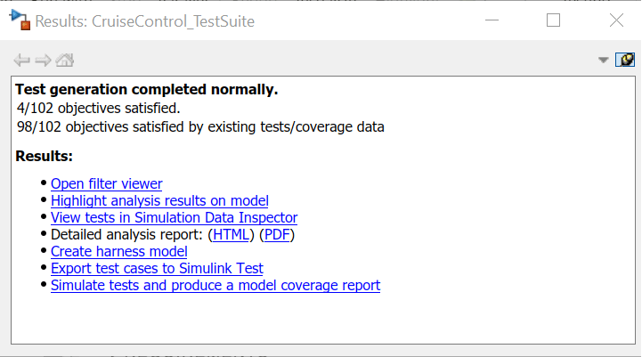
The four missing coverage objectives are satisfied, which indicates that they are not dead logic. For more information, see How to Use Simulink Design Verifier to Automatically Detect Design Errors in Your Simulink Models.
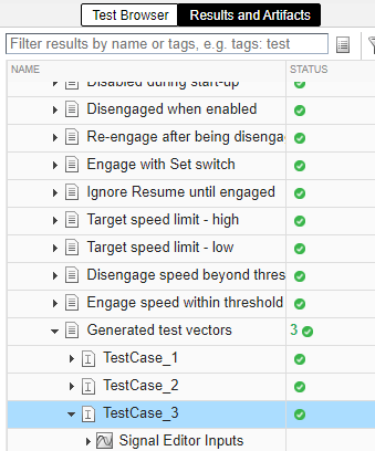
When Simulink Design Verifier generates the tests, the new test case appears in the Test Manager.
The three test vectors are iterations within that test case.

Generate Coverage Report for Full Test Suite with Automatically Generated Test Vectors
To understand how these test vectors help achieve the missing coverage objectives for the test suite, look at the coverage report.
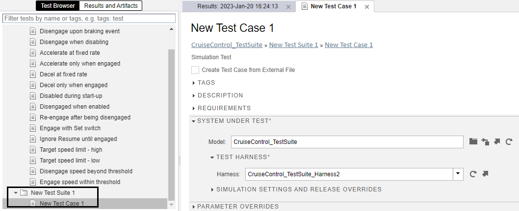
Move the new test case into the existing test suite by right-clicking on the test case and selecting Cut. Then right-click CruiseControl_TestSuite and click Paste. Right-click New Test Case 1 and select Rename to rename the test case Generated test vectors.
In the Inputs section of the Generated test vectors test case, select Include input data in test result.

Run CruiseControl_TestSuite with the new test case and look at the updated test results.

The summary of the test suite shows 18 tests passed. The generated test vectors satisfy the missing coverage, but Simulink Design Verifier does not analyze what the expected output of the model is for these input vectors. If you want to use these test cases in your testing, you must determine what the model output should be when given the generated input, and update or create requirements or tests as needed.
Generate a new coverage report by clicking the arrow icon in the Report column in the Aggregated Coverage Results section.

In the coverage report, in the Summary section, click SF: ON to open the Details section of that state.

To see the test case that analyzes the case where the model exits the ON state from the Accel substate, return to the coverage report section State "ON" and view the State "Accel" row. Test case T18, which is one of the tests cases that Simulink Design Verifier generated, satisfies this objective.
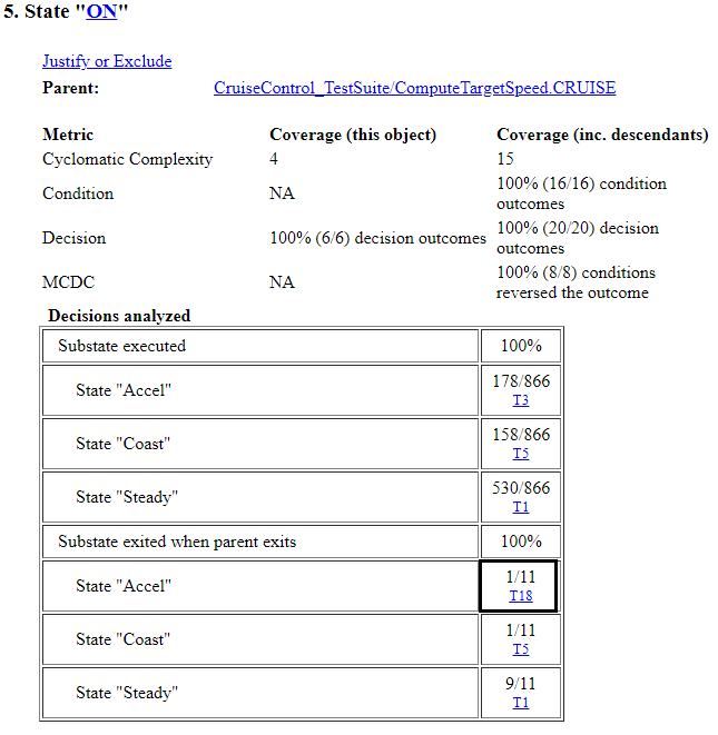
To scroll to the list of tests, click T18.

Return to Test Manager to Visualize the Test Case
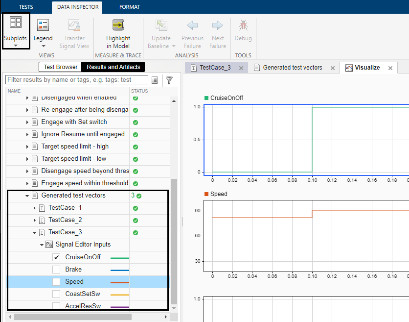
T18 is TestCase_3. To view the test case in the Test Manager, click TestCase_3.
Visualize the test case by clicking Visualize > Show Simulation Output Plots.

You can:
View the inputs by adding them using the Signal Editor Inputs drop-down menu.
Add subplots using the Subplots button.
Zoom in on specific times and pan through the test case using your cursor.
Based on your analysis of the input vectors that Simulink Design Verifier generated, you must take action to resolve the issue in your model. You can:
Write a new requirement
Modify an existing requirement
Append to or modify an existing test
Justify the missing coverage
The simplest option is to append to or modify an existing test. For this example, append additional steps to the Disengage upon braking event test case.
Click Test Browser to view test cases.
Click Disengage upon braking event.
In the System Under Test section, under Test Harness, click the arrow next to the test harness name to open the test harness.

Using the test harness, you can modify the test case to satisfy the coverage objectives that the generated test case satisfies.
See Also
Topics
- Trace Coverage Results to Requirements
- Trace Coverage Results to Associated Test Cases
- Fix Requirements-Based Testing Issues
- Generate Test Cases for Model Decision Coverage (Simulink Design Verifier)
- Extend an Existing Test Suite (Simulink Design Verifier)