Verify Model at Default Simulation Snapshot Time
This example shows how to assert that bounds on the linear system characteristics of a nonlinear Simulink® model, computed at the default simulation snapshot time of 0, are satisfied during simulation.
Open a nonlinear Simulink model. For example:
watertank
Open the Simulink Library Browser. In the Simulink Editor, on the Simulation tab, click Library Browser.
Add a model verification block to the Simulink model.
In the Simulink Control Design library, select Model Verification.
Drag and drop a block, such as the Check Pole-Zero Characteristics block, into the Simulink Editor.
The model now resembles the following figure.

Double-click the block to open the Block Parameters dialog box.

To learn more about the block parameters, see the block reference pages.
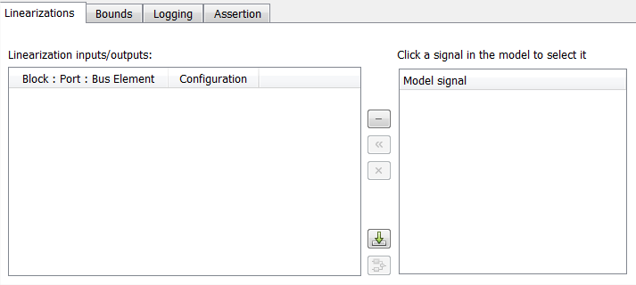
Specify the linearization input and output to compute the closed-loop poles and zeros.
Tip
If you have defined the linearization input and output in your Simulink model, click
 to automatically populate the
Linearization inputs/outputs table with I/Os
from the model.
to automatically populate the
Linearization inputs/outputs table with I/Os
from the model.To specify an input:
Click
 adjacent to the
Linearization inputs/outputs
table.
adjacent to the
Linearization inputs/outputs
table.The Block Parameters dialog box expands to display a Click a signal in the model to select it area.

In the Simulink model, click the output signal of the
Desired Water Levelblock to select it.The Click a signal in the model to select it area updates to display the selected signal.

Tip
You can select multiple signals at once in the Simulink model. All selected signals appear in the Click a signal in the model to select it area.
Click
 to add the signal to the
Linearization inputs/outputs
table.
To specify an output:
In the Simulink model, click the output signal of the
Water-Tank Systemblock to select it.The Click a signal in the model to select it area updates to display the selected signal.

Click
 to add the signal to the
Linearization inputs/outputs
table.
Note
To find the location in the Simulink model corresponding to a signal in the Linearization inputs/outputs table, select the signal in the table and click
 .
.In the Configuration drop-down list of the Linearization inputs/outputs table, select
Output Measurementfor watertank/Water-Tank System: 1.
Note
The I/Os include the feedback loop in the Simulink model. The software computes the poles and zeros of the closed-loop system.
Click
 to collapse the
Click a signal in the model to select
it area.
Specify bounds for assertion. In this example, you use the default approximate second-order bounds, specified in Bounds tab of the Block Parameters dialog box.

View the bounds on the pole-zero map by clicking Show Plot to open a plot window.

Stop the simulation if assertion fails by selecting Stop simulation when assertion fails in the Assertion tab.

Click Apply to apply all changed settings to the block.
Simulate the model by clicking
 in the plot window.
Alternatively, you can simulate the model from the Simulink Editor.
The software linearizes the portion of the model between the linearization input and output at the default simulation time of 0, specified in Snapshot times block parameter. When the software detects that a pole violates a specified bound, the simulation stops. The Diagnostics Viewer opens reporting the block that asserts.

Click Open to highlight the block that asserts in the Simulink model.

The closed-loop pole and zero locations of the computed linear system appear as
xandomarkings in the plot window. You can also view the bound violation in the plot.