Main Content

magball Simulink Model

R2026b

The Simulink® model magball includes the nonlinear Magnetic Ball Plant in a single-loop feedback system.
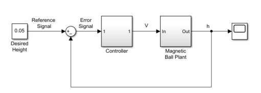
Simulink block diagram of the magball model. A Desired Height constant block with value 0.05 provides the Reference Signal to a summing junction, which computes the Error Signal by subtracting the feedback. The Error Signal passes through a Controller block, which outputs a voltage V to the Magnetic Ball Plant block. The plant outputs the ball height h, which feeds back to the summing junction and also connects to a Scope block.

The Magnetic Ball Plant subsystem is shown in the following figure.
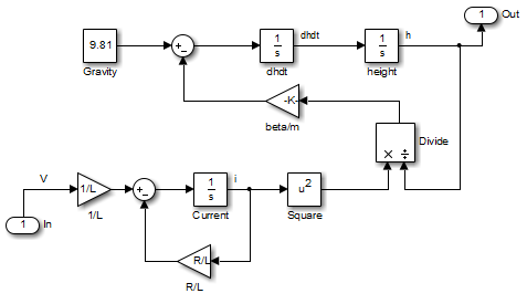
Simulink block diagram of the Magnetic Ball Plant subsystem. The upper path models the mechanical dynamics: a Gravity constant of 9.81 feeds into a summing junction along with a magnetic force term computed from a beta/m gain and a Divide block. The result integrates twice through dhdt and height integrator blocks to produce the output h. The lower path models the electrical dynamics: the input voltage V passes through a 1/L gain and a summing junction with an R/L feedback term, then integrates through a Current integrator block. The current is squared and divided by the height to compute the magnetic force that couples the two paths.

The Magnetic Ball Plant model represents an iron ball of mass M. This ball moves under the influence of the gravitational force, Mg, and an induced magnetic force, βi2h. The presence of the squared term in the induced magnetic force results in a nonlinear plant.

The inductor in the electric circuit, shown in the following figure, causes the induced magnetic force. This circuit also includes a voltage source and a resistor.
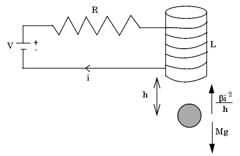
Schematic diagram of the magnetic ball system. An electric circuit on the left contains a voltage source V in series with a resistor R and an inductor L, with current i flowing through the circuit. Below the inductor, an iron ball is suspended at height h. An upward arrow represents the induced magnetic force beta i squared over h, and a downward arrow represents the gravitational force Mg acting on the ball.

The following table describes the variables, parameters, differential equations, states, inputs, and outputs of the Magnetic Ball Plant subsystem.

Variables

h is the height of the ball.

i is the current.

V is the voltage in the circuit.

Parameters

M is the mass of the ball.

g is the gravitational acceleration.

β is a constant related to the magnetic force.

L is the inductance of the coil.

R is the resistance of the circuit.

Differential equations

The height of the ball, h, is described in the following equation:

Md2hdt2=Mg−βi2h

The current in the circuit, i, is described in the following equation:

Ldidt=V−iR

States

h

dh/dt

i

InputsV
Outputsh

See Also

Topics