Isolate Model Components for Functional Testing
You can create a standalone model for the model designed using Design Model Architecture. The model slice isolates the model components and relevant signals for debugging and refinement.
Isolate Subsystems for Functional Testing
To debug and refine a subsystem of your model, create a standalone model. The standalone model isolates the subsystem and relevant signals. You can observe the subsystem behavior without simulating the entire source model. You cannot slice virtual subsystems. To isolate a virtual subsystem, first convert it to an atomic subsystem.
Isolate a Subsystem with Simulation-Based Inputs
To observe the simulation behavior of a subsystem, include logged signal inputs in the standalone model. When you configure the model slice, specify a simulation time window. For large models, observing subsystem behavior in a separate model can save time compared to compiling and running the entire source model.
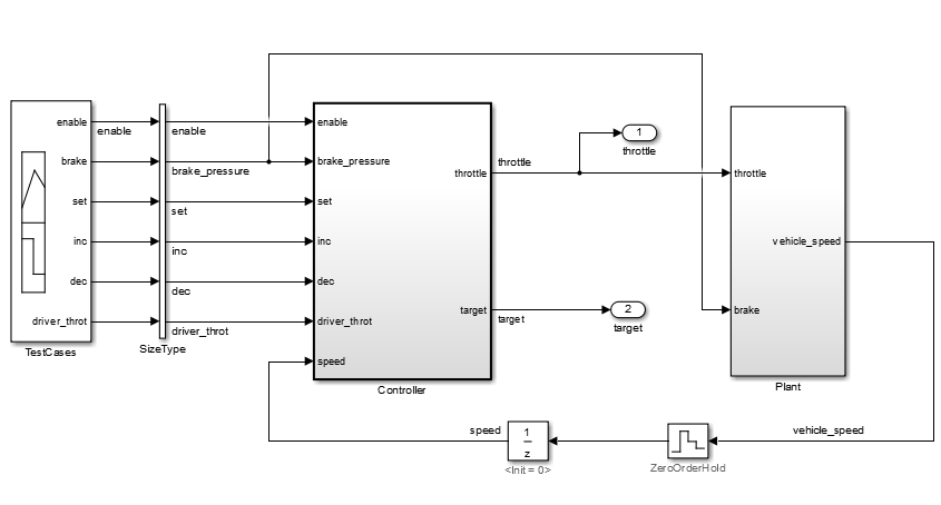
This example shows how to include simulation effects for the Controller subsystem of a cruise control system.
To open the Model Slicer, on the Apps tab, under Model Verification, Validation, and Test gallery, click Model Slicer.
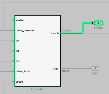
To select the starting point for dependency analysis, right-click a block, signal, or a port, and in the Model Slicer app section
 , select the Add as Starting Point
button
, select the Add as Starting Point
button  .
.To isolate the subsystem in the sliced model, right-click the subsystem, and in the Model Slicer app section, select the Slice component button
 .
.In the example model, selecting Slice component for the Controller subsystem limits the dependency analysis to the path between the starting point (the throttle outport) and the Controller subsystem.
To specify the simulation time window:
In the Model Slicer, select Simulation time window.
Click the run simulation button
 .
.Enter the simulation stop time, and click OK.

The Model slicer analyzes the model dependencies for the simulation interval.
To extract the subsystem and logged signals, click Generate slice. Enter a file name for the sliced model.
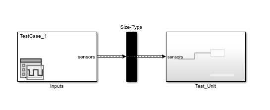
Based on the dependency analysis, a Signal Editor block supplies the signal inputs to the subsystem.
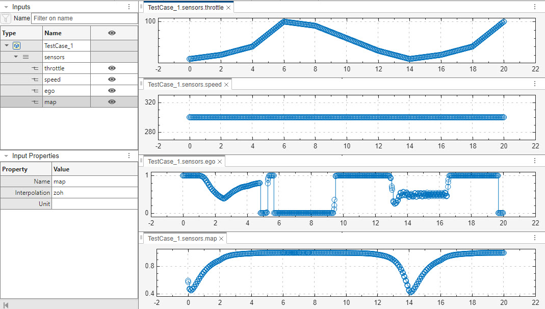
In the sliced model shown, the sliced model Signal Editor block contains one test case representing the signal inputs to the controller subsystem for simulation time 0–45 seconds.
Isolate Referenced Model for Functional Testing
To functionally test a referenced model, you can create a slice of a referenced model treating it as an open-loop model. You can isolate the simplified open-loop referenced model with the inputs generated by simulating the close-loop system.
This example shows how to slice the referenced model controller of a fault-tolerant fuel control system for functional testing. To create a simplified open-loop referenced model for debugging and refinement, you generate a slice of the referenced controller.
Open the Model
The fault-tolerant fuel control system model contains a referenced model controller fuel_rate_control.
open_system('sldvSlicerdemo_fuelsys');

Slice the Referenced Model
To analyze the fuel_rate_control referenced model, you slice it to create a standalone open-loop model. To open the Model Slice Manager, open the Apps gallery, and select Model Slicer. Alternatively, right-click the fuel_rate_control model and in the Model Slicer app section, select the Slice component button. When you open the Model Slice Manager, the Model Slicer compiles the model. You then configure the model slice properties.
Note: The simulation mode of the sldvSlicerdemo_fuelsys model is Accelerator mode. When you slice the referenced model, the software configures the simulation mode to Normal mode and sets it back to its original simulation mode while exiting the Model Slicer.
Select Starting Point
Open the fuel_rate_control model, right-click the fuel-rate port, and in the Model Slicer app section, select the Add as Starting Point button. The Model Slicer highlights the upstream constructs that affect the fuel_rate.

Generate Slice
a. In the Model Slice Manager dialog box, select the Simulation time window.
b. Click Run simulation.
c. For the Stop time, enter 20. Click OK.
d. Click Generate Slice. The software simulates the sliced referenced model by using the inputs of the close-loop sldvSlicerdemo_fuelsys model.

For the sliced model, in the Signal Editor window, one test case is displayed that represents the signals input to the referenced model for simulation time 0–20 seconds.

See Also
Model Slicer Considerations and Limitations | Highlight Functional Dependencies