Propagate Variant Conditions to Define Variant Regions Using Variant Source and Variant Sink Blocks
Simulink® automatically propagates the variant conditions from the Variant Source and Variant Sink blocks to their connecting blocks. The propagation of variant conditions enables Simulink to determine which components of the model remain active during simulation. Simulink then deactivates the model components associated with the inactive choices and highlights the active connections.
Tip
The variant condition annotations on model components help you visualize the propagated conditions. To view the annotations, on the Debug tab, select Information Overlays > Variant Legend. If Variant Legend is not available, on the Debug tab, select Information Overlays > Variant Conditions. For more information, Visualize Propagated Variant Conditions in Variant Conditions Legend.
Variant Source and Variant Sink Blocks
Consider the slexVariantSourceAndSink model containing two Variant Source blocks Variant Source1 and Variant Source2, and a Variant Sink block. The variant conditions at the inports and the outports of the Variant Source and the Variant Sink blocks determine the activation and deactivation of the blocks connected to them. V and W are the variant control variables and are defined in the PostLoadFcn callback of the model.
open_system("slexVariantSourceAndSink");

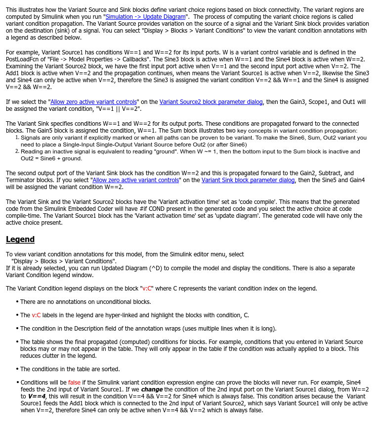
When you simulate the model, the variant conditions are propagated as follows:

In
Variant Source1, whenW == 1evaluates totrue, theSine3block is active, and whenV == 4evaluates totrue, theSine4block is active.In
Variant Source2, whenV == 1evaluates totrue, theSine1block is active, and whenV == 2, theAdd1block is active.For the
Variant Source1block to be active, theAdd1block must be active. This further propagates to theSine3block andSine4blocks, making theSine3block active whenV == 2andW == 1evaluate totrueand theSine4block active whenV == 2andW == 2evaluate totrue.The
Gain3block is active whenV == 1orV == 2evaluates totrue. The variant condition is further propagated toScope1andOut1.The blocks connected to the outport of the
Variant Sinkblock are active whenW == 1(Gain5), orW == 2(Sine,Subtract,Terminator).The
Sumblock illustrates two key concepts of variant condition propagation: Signals are variant only if explicitly marked or when all paths can be proven to be variant. For example, theSine6,Sum, andOut2blocks are unconditional. To mark the blocks as conditional, place a single-input, single-output Variant Source block beforeOut2or afterSine6. Reading an inactive signal is equivalent to reading ground. For example, whenW == 1evaluates tofalse, the bottom input to theSumblock is inactive andOut2 = Sine6 + ground.
If you set Allow zero active variant controls of the Variant Sink block to on, Simulink® also propagates the variant conditions to the unconditional blocks Sine5 and Gain4 of the variant region also. The variant conditions on Sine5 and Gain4 are the logical OR of the variant conditions, W == 1 and W == 2 of the Variant Sink block. When W == 1 and W == 2 evaluate to false, the condition W == 1 OR W == 2 evaluates to false, thus making Sine5 and Gain4 inactive. This ensures that Sine5 and Gain4 are removed from simulation and are not left unused when the Variant Sink block is inactive.
Generate Code for Variant Source and Variant Sink Blocks
For an example on generating code, see Generate Code for Variant Source and Variant Sink Blocks (Simulink Coder).
Related Topics
You can also select a web site from the following list:
Americas
- América Latina (Español)
- Canada (English)
- United States (English)
Europe
- Belgium (English)
- Denmark (English)
- Deutschland (Deutsch)
- España (Español)
- Finland (English)
- France (Français)
- Ireland (English)
- Italia (Italiano)
- Luxembourg (English)
- Netherlands (English)
- Norway (English)
- Österreich (Deutsch)
- Portugal (English)
- Sweden (English)
- Switzerland
- United Kingdom (English)