Repeat an Algorithm Using a For-Each Subsystem
To repeat an algorithm, you can iterate the algorithm over signals, subsystems, and parameters that are grouped into arrays and structures. This page gives examples of how to convert an inefficiently complex repetitive algorithm into a compact form that is easier to manage.
If you repeat algorithms in a diagram by copying and pasting blocks and subsystems, maintaining the model can become difficult. Individual signal lines and subsystems can crowd the diagram, reducing readability and making simple changes difficult. Variables can also crowd workspaces, reducing model portability. A model can develop these efficiency issues as you add to the design over time.
Explore Example Model
Open the example to access the models that are used in this topic.
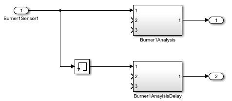
The RepeatAlgorithm model processes and analyzes sensor data from three burners, which contain three sensors each. Each subsystem uses the same algorithm for each burner, but different variables, which the model loads into the base workspace. You can simplify the model by using for-each subsystems.
Open the RepeatAlgorithm model.
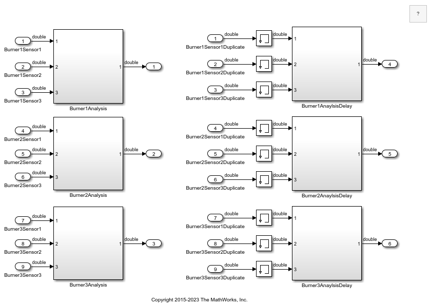
Each of the subsystems on the left receives three input signals. The subsystems on the right receive the same input signals via duplicate Inport blocks, but Memory blocks delay the input signals before they enter the subsystems on the right.
Open the Burner1Analysis subsystem.
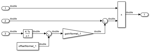
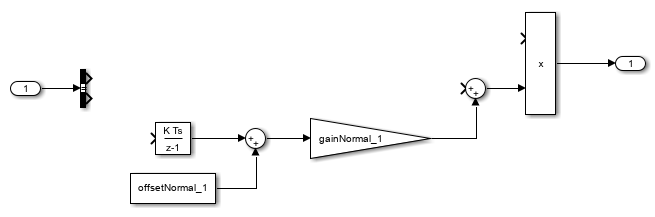
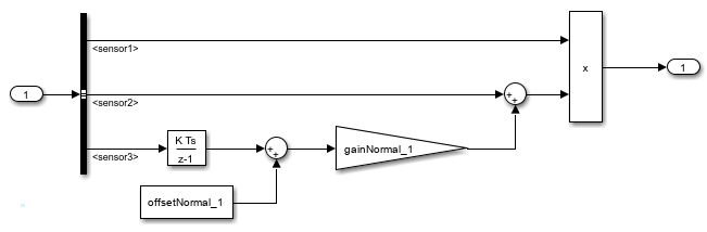
The Burner1Analysis subsystem executes an algorithm by using the base workspace variables as parameters in blocks such as Constant and Discrete-Time Integrator blocks. The Burner2Analysis and Burner3Analysis subsystems execute the same algorithm as the Burner1Analysis subsystem but use different workspace variables to parameterize the blocks.
Open the Burner1AnalysisDelay subsystem.
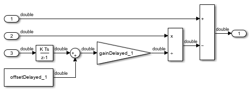
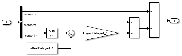
The Burner1AnalysisDelay subsystem executes a different algorithm with different base workspace variables. The Burner2AnalysisDelay and Burner3AnalysisDelay subsystems repeat this algorithm.
In the toolstrip, on the Modeling tab, click Model Settings. Open the Data Import/Export pane of the Configuration Parameters dialog box. The model uses the variables SensorsInput and t as simulation inputs. During simulation, each of the nine columns in the SensorsInput matrix variable provides input data for an Inport block at the top level of the model.
Identify Opportunities to Simplify Model
This example has multiple subsystems that implement the same algorithms. To simplify the model, one for-each subsystem can replace each set of subsystems that represents the same algorithm. An array of buses can provide structured input for the for-each subsystems.
These features can make the model more compact and easier to manage.
Remove Redundant Blocks
With the goal in mind, remove the redundant blocks from the block diagram.
For the subsystems that contain
Burner2andBurner3in their names, delete all the blocks, including the Subsystem blocks.For the subsystem named
Burner1Analysis, delete the Inport blocks namedBurner1Sensor2andBurner1Sensor3.For the subsystem named
Burner1AnalysisDelay, delete the Inport blocks namedBurner1Sensor2DuplicateandBurner1Sensor3Duplicateand the corresponding Memory blocks.Replace the Inport block named
Burner1Sensor1Duplicatewith a branched line from the Inport block namedBurner1Sensor1.Resize the two remaining Subsystem blocks and reorganize the block diagram.
Simplify Interfaces with Buses
To group related signals into a single structured interface, use buses. Buses reduce line density and improve model readability.
Each subsystem in the example model requires three input signals. A bus can group these
three signals for each subsystem. To pass each bus as structured input to the for-each
subsystems via an array of buses, the bus must be defined by a Simulink.Bus
object.
Open the Type Editor. From the Simulink® Toolstrip, on the Modeling tab, in the Design gallery, click Type Editor.
Create a
Simulink.Busobject in the base workspace namedSensorDatawith three elements:sensor1,sensor2, andsensor3.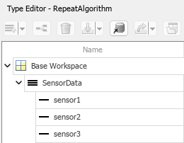
Select the remaining Inport block. In the Type Editor, right-click the bus object named
SensorData. Then, select Assign type to selected blocks and ports.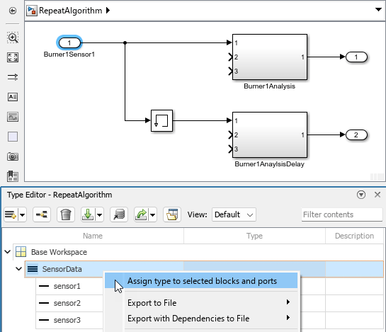
The data type of the Inport block becomes
Bus:
								SensorData
. The block output becomes a bus that contains the three signal elements:sensor1,sensor2, andsensor3.In the subsystem named
Burner1Analysis, update the interface for the bus input. For-each subsystems do not support In Bus Element blocks. Therefore, use an Inport block and a Bus Selector block.Delete the output signal lines of the three Inport blocks.
Delete the Inport blocks for ports 2 and 3.
Connect a Bus Selector block to the Inport block for port 1.
In the Bus Selector block dialog box, in the Elements in the bus list, select the signals named
sensor1,sensor2, andsensor3. Then, to add the signals to the Output elements list, click .
.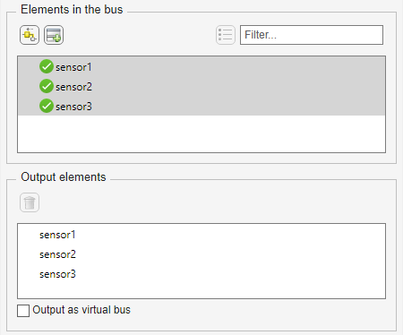
The Bus Selector block extracts the three signals from the input bus. Other blocks in the model can use the extracted signals.
In the
Burner1Analysissubsystem, connect the signals:Connect
sensor1to the Product block.Connect
sensor2to the Sum block.Connect
sensor3to the Discrete-Time Integrator block.
In the subsystem named
Burner1AnalysisDelay, use a Bus Selector block to extract the signals from the bus. Use the same steps as you did in the subsystem namedBurner1Analysisand connect the signals:Connect
sensor1to the Subtract block.Connect
sensor2to the Divide block.Connect
sensor3to the Discrete-Time Integrator block.
Repeat an Algorithm
A For Each Subsystem block partitions an input signal and sequentially executes an algorithm on each partition. For example, if the input to the subsystem is an array of six signals, you can configure the subsystem to execute the same algorithm on each of the six signals.
You can use for-each subsystems to repeat an algorithm in an iterative fashion. This approach improves model readability and makes it easy to change the repeated algorithm.
Add two For Each Subsystem blocks to the model. Name one of the subsystems
BurnerAnalysis. Name the other subsystemBurnerAnalysisDelay.Copy the contents of the subsystem named
Burner1Analysisinto the subsystem namedBurnerAnalysis. Before you paste the blocks, delete the Inport and Outport blocks in the for-each subsystem.In the For Each block dialog box in the
BurnerAnalysissubsystem, select the check box to partition the inputIn1.Copy the contents of the subsystem named
Burner1AnalysisDelayinto the subsystem namedBurnerAnalysisDelay.In the For Each block dialog box in the
BurnerAnalysisDelaysubsystem, select the check box to partition the inputIn1.At the top level of the model, delete the subsystems named
Burner1AnalysisandBurner1AnalysisDelay. Connect the new For Each Subsystem blocks in their place.On the Signal Attributes tab of the
Burner1Sensor1Inport block dialog box, set Port dimensions to3.The block output is a three-element array of buses. The for-each subsystems in the model repeat an algorithm for each of the three buses in the array.
Create a
Simulink.SimulationData.Datasetobject that the Inport block can use to import the simulation data. You can use this code to create the object and store it in the variableSensorsInput.% First, create an array of structures whose field values are % timeseries objects. for i = 1:3 % Burner number % Sensor 1 eval(['tempInput(1,' num2str(i) ').sensor1 = ' ... 'timeseries(SensorsInput(:,' num2str(3*(i-1)+1) '),t);']) % Sensor 2 eval(['tempInput(1,' num2str(i) ').sensor2 = ' ... 'timeseries(SensorsInput(:,' num2str(3*(i-1)+2) '),t);']) % Sensor 3 eval(['tempInput(1,' num2str(i) ').sensor3 = ' ... 'timeseries(SensorsInput(:,' num2str(3*(i-1)+3) '),t);']) end % Create the Dataset object. SensorsInput = Simulink.SimulationData.Dataset; SensorsInput = addElement(SensorsInput,tempInput,'element1'); clear tempInput t i
The code first creates a variable
tempInputthat contains an array of three structures. Each structure has three fields that correspond to the signal elements in the bus typeSensorData, and each field stores a MATLAB®timeseriesobject. Eachtimeseriesobject stores one of the nine columns of data from the variableSensorsInput, which stores the simulation input data for each of the sensors.The code then overwrites
SensorsInputwith a newSimulink.SimulationData.Datasetobject and addstempInputas an element of the object.Set the Input configuration parameter to
SensorsInput.Since
SensorsInputprovides simulation input data in the form oftimeseriesobjects, you do not need to specify a variable that contains time data.Create an array of structures that initializes the remaining Memory block, and store the array in the variable
initForDelay. Specify the structure fields with the values of the existing initialization variables, such asinitDelay_1_sensor1.for i = 1:3 % Burner number % Sensor 1 eval(['initForDelay(' num2str(i) ').sensor1 = ' ... 'initDelay_' num2str(i) '_sensor1;']) % Sensor 2 eval(['initForDelay(' num2str(i) ').sensor2 = ' ... 'initDelay_' num2str(i) '_sensor2;']) % Sensor 3 eval(['initForDelay(' num2str(i) ').sensor3 = ' ... 'initDelay_' num2str(i) '_sensor3;']) end
To view the contents of the new variable
initForDelay, double-click the variable name in the base workspace. The variable contains an array of three structures that each has three fields:sensor1,sensor2, andsensor3.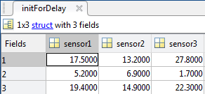
In the Memory block dialog box, set Initial condition to
initForDelay.The Memory block output is an array of buses that requires initialization. Each signal element in the array of buses acquires an initial value from the corresponding field in the array of structures.
Organize Parameters into Arrays of Structures
The base workspace contains many variables that the example model uses for block parameters. To reduce the number of workspace variables, package them into arrays of structures, and use the individual structure fields to specify block parameters.
A For Each Subsystem block can partition an array of values that you specify as a mask parameter. Each iteration of the subsystem uses a single partition of the array to specify block parameters. If you specify the parameter as an array of structures, each iteration of the subsystem can use one of the structures in the array.
Create an array of structures that parameterizes the For Each Subsystem block named
BurnerAnalysis, and store the array in the variableparamsNormal. Specify the structure fields by using the values of existing parameter variables, such asgainNormal_1,offsetNormal_1, andinitDelayed_1.for i = 1:3 eval(['paramsNormal(' num2str(i) ').gain = gainNormal_' num2str(i) ';']) eval(['paramsNormal(' num2str(i) ').offset = offsetNormal_' num2str(i) ';']) eval(['paramsNormal(' num2str(i) ').init = initNormal_' num2str(i) ';']) end
The variable contains an array of three structures that each has three fields:
gain,offset, andinit.In the model, right-click the
BurnerAnalysisfor-each subsystem and select Mask > Create Mask and select Create Mask.On the Parameters & Dialog pane of the dialog box, under Parameter, click Edit. For the new mask parameter, set Prompt to
Parameter
								structure
and Name toparamStruct. Click Save Mask.In the mask for the
BurnerAnalysissubsystem, set Parameter structure toparamsNormal.Open the subsystem. In the For Each block dialog box, on the Parameter Partition pane, select the check box to partition the parameter
paramStruct. Set Partition dimension to2.For the blocks in the subsystem, set these parameters.
Block Parameter Name Parameter Value Gain Gain paramStruct.gainDiscrete-Time Integrator Initial condition paramStruct.initConstant Constant value paramStruct.offsetCreate an array of structures that parameterizes the
BurnerAnalysisDelayfor-each subsystem, and store the array in the variableparamsForDelay.for i = 1:3 eval(['paramsForDelay(' num2str(i) ').gain = gainDelayed_' num2str(i) ';']) eval(['paramsForDelay(' num2str(i) ').offset = offsetDelayed_' num2str(i) ';']) eval(['paramsForDelay(' num2str(i) ').init = initDelayed_' num2str(i) ';']) end
At the top level of the model, right-click the
BurnerAnalysisDelayfor-each subsystem and select Create Mask.On the Parameters & Dialog pane of the dialog box, under Parameter, click Edit. For the new mask parameter, set Prompt to
Parameter
								structure
and Name toparamStruct. Click Save Mask.In the mask for the For Each Subsystem block, set Parameter structure to
paramsForDelay.Open the subsystem. In the For Each block dialog box, on the Parameter Partition pane, select the check box to partition the parameter
paramStruct. Set Partition dimension to2.For the blocks in the subsystem, set these parameters.
Block Parameter Name Parameter Value Gain Gain paramStruct.gainDiscrete-Time Integrator Initial condition paramStruct.initConstant Constant value paramStruct.offsetClear the unnecessary variables from the base workspace.
% Clear the old parameter variables that you replaced
% with arrays of structures
clear -regexp _

% Clear the iteration variables
clear i
The model requires few variables in the base workspace.
Inspect Converted Model
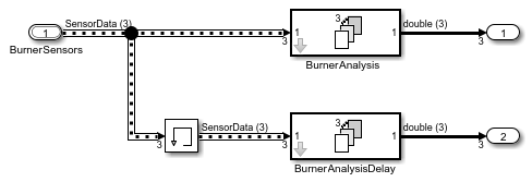
To view the new signal and subsystem organization, update the diagram.
The model input is an array of three buses. The model uses two for-each subsystems to execute the two algorithms on each of the three buses in the input array.
In the base workspace, arrays of structures replace the many variables that the model used. Mathematically, the modified model behaves the same way it did when you started because the arrays of structures contain the values of all the old variables.
Tip
You can log nonbus signals in a for-each subsystem. However, you cannot use signal logging for buses or arrays of buses from within a for-each subsystem. Either use a Bus Selector block to select the bus elements that you want to log or add an Outport block outside of the subsystem and then log that signal. For details, see Log Signals in For-Each Subsystems.
Additional Examples of Working with For-Each Subsystems
Vectorize Algorithms Using For-Each Subsystems
This example shows how to simplify modeling of vectorized algorithms. Using For Each Subsystem blocks simplifies a model where three input signals are filtered by three identical Transfer Fcn blocks. This example also shows how to add more control to the filters by changing their coefficients for each iteration of the subsystem.
This model uses identical Transfer Fcn blocks to independently process each signal. A Vector Concatenate block concatenates the resulting output signals. This repetitive process is graphically complex and difficult to maintain. Adding another signal also requires significant reworking of the model.
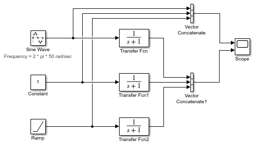
You can simplify this model by replacing the repetitive operations with a single For Each Subsystem block.
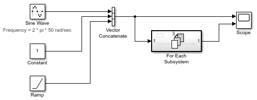
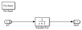
The For Each Subsystem block contains a For Each block and a model representing the algorithm of the three blocks it replaces by way of the Transfer Fcn block. The For Each block specifies how to partition the input signal vector into individual elements and how to concatenate the processed signals to form the output signal vector. Every block that has a state maintains a separate set of states for each input element processed during a given execution step.
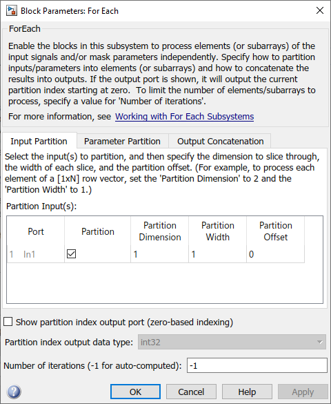
For this example, the input signal is selected for partitioning. The
Partition Dimension and Partition Width
parameters on the For Each block are both set to 1 for the
input.
You can scale up this approach to add more signals without having to change the model significantly. This approach is easily scalable and graphically simpler.
Model Parameter Variation Without Changing Model Structure. This example shows how to model parameter variation in an algorithm. It uses the for-each subsystem partitioning model from the previous example and creates different filters for each input signal while retaining model simplicity. An array of filter coefficients is fed to the For Each Subsystem block as a mask parameter marked for partitioning. In each iteration of the For Each Subsystem block, a partition of the filter coefficient array is fed to the Transfer Fcn block.
Open the model
ex_ForEachSubsystem_Partitioning.Create a mask for the For Each Subsystem block and add an editable mask parameter. Set the name to
FilterCoeffsand the prompt toFilter Coefficient Matrix. For information on how to add a mask parameter, see Create a Simple Mask.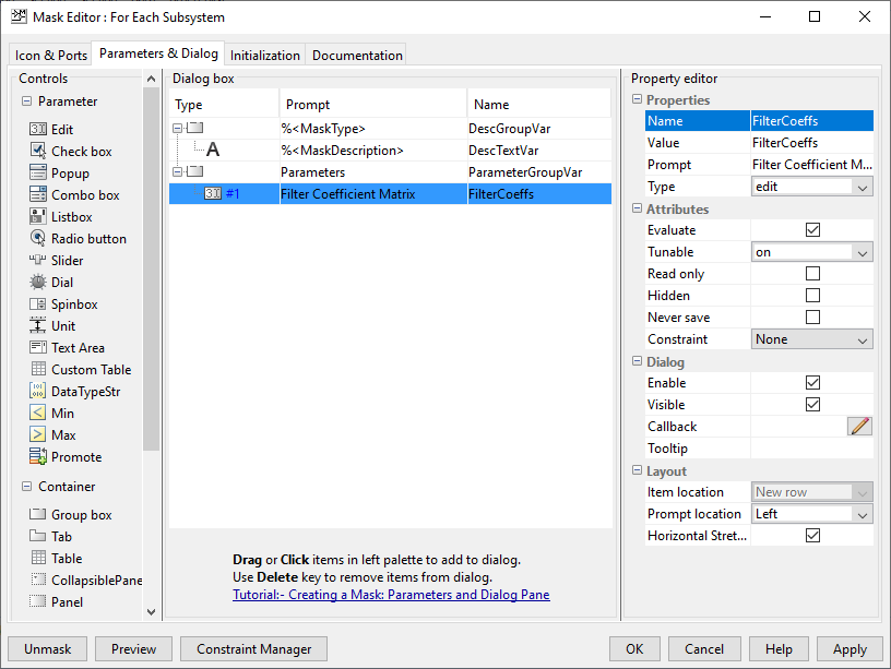
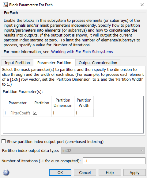
Open the For Each Subsystem block. Inside the subsystem, open the For Each block dialog box.
In the Parameter Partition tab, select the check box next to the FilterCoeffs parameter to enable partitioning of this parameter. Keep the Partition Width and Partition Dimension parameters at their default value of 1.
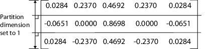
Double-click the For Each Subsystem block and enter your filter coefficient matrix, having one row of filter coefficients for each input signal. For example, enter
[0.0284 0.2370 0.4692 0.2370 0.0284; -0.0651 0 0.8698
										0 -0.0651; 0.0284 -0.2370 0.4692 -0.2370 0.0284]
to implement different fourth-order filters for each input signal.In the For Each Subsystem block, double-click the Transfer Fcn block and enter
FilterCoeffsfor the Denominator Coefficients parameter. This setting causes the block to get its coefficients from the mask parameter.
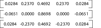
The For Each Subsystem block slices the input parameter into horizontal partitions of width 1, which is equivalent to one row of coefficients. The parameter of coefficients starts as a single array.
It transforms from a single array into three rows of parameters.
Improved Code Reuse Using For-Each Subsystems
This example shows how you can design models to improve code reuse when you have two
or more identical For Each Subsystem blocks. Consider the
ForEachReuse model.
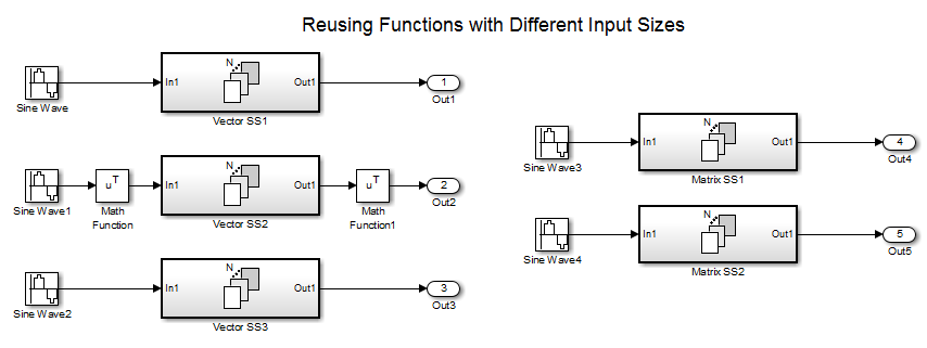
The intent is for the three subsystems — Vector SS1,
Vector SS2, and Vector SS3 — to apply the
same processing to each scalar element of the vector signal at their respective inputs.
Because these three subsystems perform the same processing, it is desirable for them to
produce a single shared Output (and Update) function for all three subsystems in the code
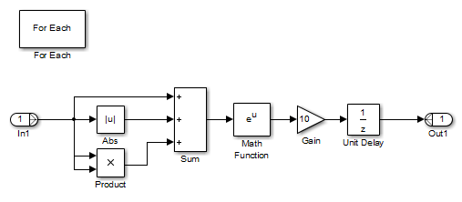
generated for this model. For example, the Vector SS3 subsystem
contains these blocks.
To generate a single shared function for the three subsystems, the configuration of the
partitioning they perform on their input signals must be the same. For
Vector SS1 and Vector SS3, this
configuration is straightforward because you can set the partition dimension and
width to 1. However, in order for Vector SS2 to also
partition its input signal along dimension 1, insert a Math
Function block to transpose the 1-by-8 row vector into an 8-by-1
column vector. To convert the output of the subsystem back to a 1-by-8 row
vector using a second Math Function block set to the
transpose operator. A reusable shared function
can also be generated for the remaining two subsystems that process matrix
signals. For more information about generating reusable code from subsystems,
see Generate Reentrant Code from Subsystems (Embedded Coder).
Limitations of For-Each Subsystems
The For Each Subsystem block has these limitations and workarounds.
| Limitation | Workaround |
|---|---|
You cannot log a bus or an array of buses directly in the for-each subsystem. | Use one of these approaches:
|
You cannot log a signal inside a referenced model that is inside a for-each subsystem if either of these conditions exists:
| For the first condition, use accelerator mode. For the second condition, use normal or rapid accelerator mode. |
You cannot log the states of the blocks in a for-each subsystem. | Save and restore the simulation state. |
You cannot use Normal mode to simulate a Model block inside a for-each subsystem. | Use accelerator or rapid accelerator mode. |
Reusable code is generated for two for-each subsystems with identical contents if their input and output signals are vectors (1-D or 2-D row or column vector). For n-D input and output signals, reusable code is generated only when the dimension along which the signal is partitioned is the highest dimension. | Permute the signal dimensions to transform the partition dimension and the concatenation dimension to the highest nonsingleton dimension for n-D signals. |
The For Each Subsystem block does not support these features:
You cannot include these blocks or S-functions inside a for-each subsystem:
Data Store Memory, Data Store Read, or Data Store Write blocks
The From Workspace block if the input data uses the
Structure with Timeformat and has an empty time fieldTo File blocks
Goto and From blocks that cross the subsystem boundary
Referenced model with simulation mode set to normal
Shadow Inports
ERT S-functions
For a complete list of the blocks that support for-each subsystems, enter
showblockdatatypetablein the MATLAB Command Window.
You cannot use these types of signals inside the subsystem:
Signals with a storage class other than
Autoor other than a structured storage class defined using the Embedded Coder® DictionaryFrame signals on subsystem input and output boundaries
Variable-size signals of more than one dimension
Creation of a linearization point inside the subsystem
Propagating the Jacobian flag for the blocks inside the subsystem. You can check this condition in MATLAB using
J.Mi.BlockAnalyticFlags.jacobian, whereJis the Jacobian object. To verify the correctness of the Jacobian of the For Each Subsystem block:Look at the tag of the for-each subsystem Jacobian. If it is
“not_supported”, then the Jacobian is incorrect.Move each block out of the for-each subsystem and calculate its Jacobian. If any block is
“not_supported”or has a warning tag, the for-each subsystem Jacobian is incorrect.
You cannot perform these types of code generation:
Generation of a Simulink Coder™ S-function target
Simulink Coder code generation under both of these conditions:
A Stateflow® or MATLAB Function block resides in the subsystem.
This block tries to access global data outside the subsystem, such as Data Store Memory blocks or
Simulink.Signalobjects ofExportedGlobalstorage class.
In some cases, a model using a for-each subsystem may take longer to simulate in normal mode than it would take if the model were implemented using separate subsystems.
Local solvers are not supported for referenced models inside for-each subsystems. For more information, see Use Local Solvers in Referenced Models.