Graphically Manage Shared Interfaces, Data Types, and Constants
The Architectural Data section of a Simulink® data dictionary enables interfaces, data types, and constants to be authored, managed, and shared between components and compositions modeled in Simulink. The Architectural Data section provides scalability for system-level and multicomponent designs by containing these shared elements in a central location. For programmatic workflows related to the Architectural Data section, see Create Architectural Data Object and Use It to Configure Architectural Data.
You can configure architectural data and apply your changes to a model using this basic workflow:
Create a data dictionary.
Design interface, data types, and constants with the Architectural Data Editor.
Link the data dictionary containing architectural data to a Simulink or architecture model.
Create Simulink Data Dictionary and Open Architectural Data Section for Editing
To create a data dictionary programmatically, see Store Data in Dictionary Programmatically or Create Architectural Data Object and Use It to Configure Architectural Data.
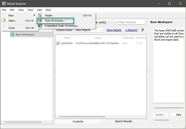
To create a data dictionary outside the context of a model open Model Explorer. From the toolbar select File, New, and then Data Dictionary.
To create a data dictionary from a Simulink model:
Open the
f14model, which loads design data into the base workspace.openExample('f14')Save a copy of the model to your working folder location. Open the copy.
In the Simulink Editor, on the Modeling toolstrip, open the Design menu, select Link to Data Dictionary.
In the Model Properties dialog box, select New to create a data dictionary.
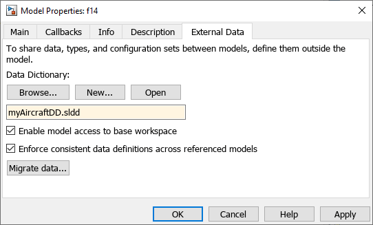
Name the data dictionary, save it, and click Apply.
Design Data Types, Interfaces, and Constants Using Architectural Data Editor
Once you create your data dictionary, you can add and edit architectural data using the Architectural Data Editor. This tool allows you to author elements shared outside of the context of a particular component or composition and allow multiple team members to define and manage these elements.
Open Architectural Data Editor
To open the editor from a Simulink model already linked to a data dictionary:
In the bottom left of the model, select the Model data icon
 , and then select External
Data. This opens Model Explorer.
, and then select External
Data. This opens Model Explorer.In Model Explorer select the Architectural Data node to expose and select the Open Architectural Data Editor button.

To open the editor from outside the context of a model, use one of these methods:
In the MATLAB® Current Folder browser, navigate to and double-click the
.slddfile to open Model Explorer. Expand the data dictionary file and select Architectural Data, then click Open Architectural Data Editor from the Dialog pane.Use the
showfunction on an Architectural Data object created usingSimulink.dictionary.archdata.createorSimulink.dictionary.archdata.open.Enter
archdataeditorat the MATLAB command line.
Add and Configure Data Using Architectural Data Editor
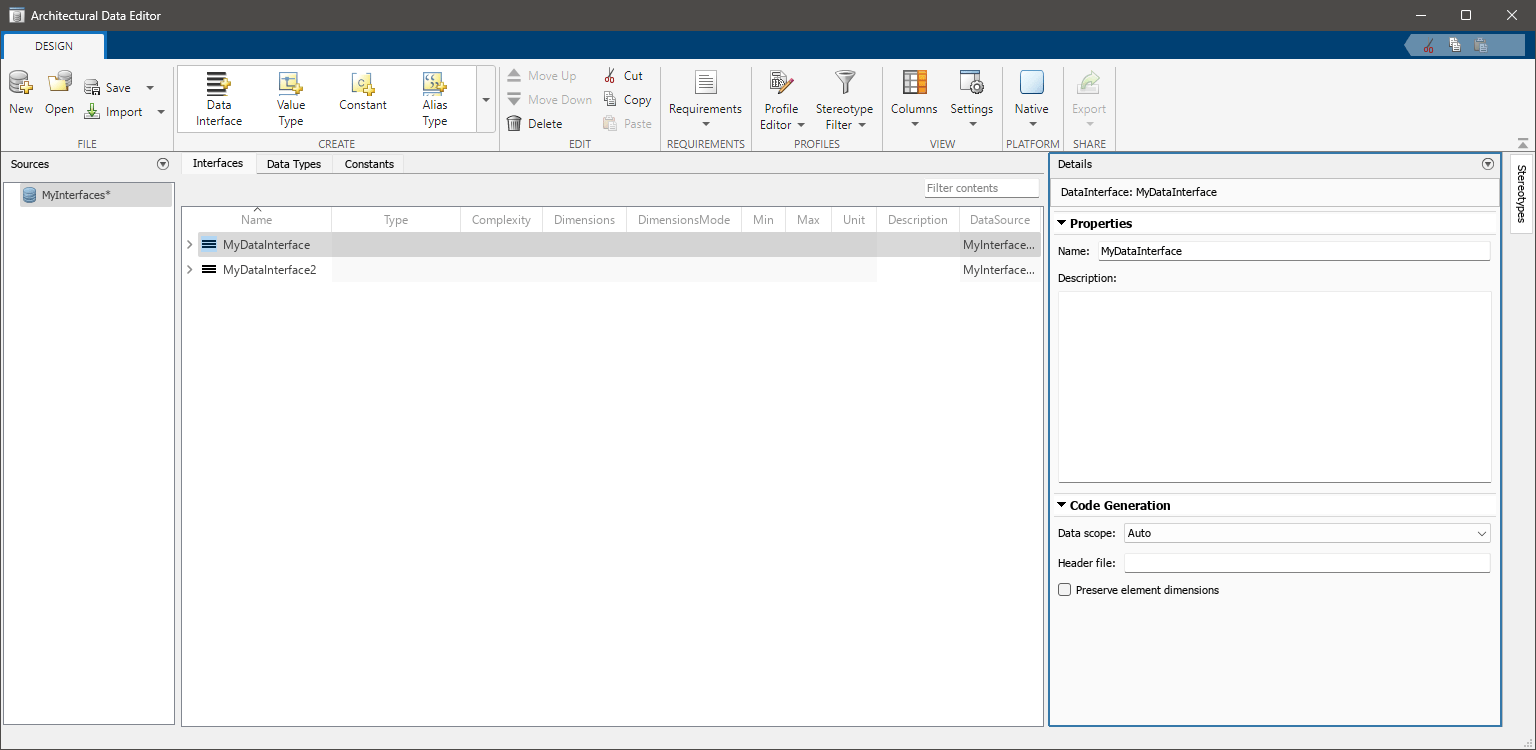
With the Architectural Data Editor, you can create, configure, and manage architectural data.
Create — On the toolstrip, in the Create section, add data type definitions, interfaces, and constants. Data types, interfaces, and constants each have a dedicated tab for data management.
Configure — In the right panel, use the Details pane to configure your data. The Details pane can also display platform-specific properties.
For example, when you open a Simulink data dictionary linked to a model that is mapped to a Native platform, the Details pane displays a Code Generation pane. You can then define Data scope and Header file. For more information on how to determine these settings, see Control File Placement of Custom Data Types (Embedded Coder). To preserve dimensions of bus objects that contain multidimensional bus elements, select the Preserve element dimensions option.
Manage — You can filter, sort, and search data on the Interfaces, Data Types, and Constants tabs.
Link Data Dictionary to Model
To link an existing data dictionary from the Simulink model toolstrip, on the Modeling tab, open the Design gallery and select Link to Data Dictionary. In the Model Properties dialog box, click Browse to select a data dictionary. Select Apply then OK.
See Also
Architectural Data Editor | Property Inspector | Simulink.dictionary.ArchitecturalData | Simulink.dictionary.archdata.open
Related Topics
You can also select a web site from the following list:
Americas
- América Latina (Español)
- Canada (English)
- United States (English)
Europe
- Belgium (English)
- Denmark (English)
- Deutschland (Deutsch)
- España (Español)
- Finland (English)
- France (Français)
- Ireland (English)
- Italia (Italiano)
- Luxembourg (English)
- Netherlands (English)
- Norway (English)
- Österreich (Deutsch)
- Portugal (English)
- Sweden (English)
- Switzerland
- United Kingdom (English)