Events in Schedule Editor
An event is a construct that represents an action, transition, or condition. You can broadcast events from within a model hierarchy. The Schedule Editor allows you to create and manage partitions and schedule the execution of your model. You can bind an event to an aperiodic partition that is scheduled, based on priority, for execution when the event is broadcast. Events simplify system creation and provide more flexibility during scheduling.
Events can connect blocks that detect important conditions with a partition to schedule
the execution of the partition when the conditions occurs. You can send Schedule Editor events
from Stateflow® charts using the send keyword. You can also configure event
triggers on the Inport or In Bus
Element block, and manage the events in the Schedule Editor.
Event Management in the Schedule Editor
Each model in a model hierarchy has its own Events panel in the Schedule Editor, that contains all the events present in the model and the model's children. When you open the Schedule Editor and update the diagram, all partitions and events present in the model appear in the Schedule Editor. Through the Events panel, you can:
Create an event.
Delete an event.
Rename an event.
Get an event.
Bind an event to a partition.
Unbind an event from a partition.
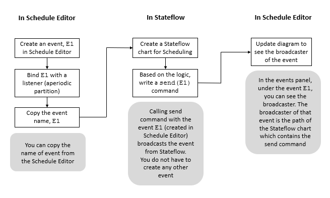
You can create a Stateflow chart for scheduling and use the send operator to broadcast
an event. Then, in the Schedule Editor, in Events, create an event of
the same name. Update the diagram to see the broadcaster of that event which is the
Stateflow chart.
You can also configure event triggers on the Inport or In Bus Element block that represents the port. Then, in the Schedule Editor, specify the partition to execute in response to each event and schedule the priority of execution. By configuring event triggers on input ports, you can model and simulate quality of service effects. The table summarizes the event triggers you can configure on input ports. For each input port, you can configure one event trigger for each input event.
| Input Event | Input Event Description | Event Trigger Object |
|---|---|---|
| Input write | Value for input port updates. | simulink.event.InputWrite |
| Input write timeout | Input port value does not update within a specified amount of time. | simulink.event.InputWriteTimeout |
| Input write lost | Input port value update overwrites unprocessed data. | simulink.event.InputWriteLost |
The Events panel in the Schedule Editor shows you the event tree. Under every event, you can see the broadcasters and listeners of that event.
When an event is bound to a partition, the event name appears on the left side of the partition. When multiple events are bound to a partition, the number of bound events appears on the left side of the partition. When multiple events are bound to a partition, in the Order table, the Trigger column displays the number of events to which the partition is bound.
Naming
Unique names are enforced for events within a model and within a model hierarchy.
Within a model hierarchy, the model name prepends the event name. For example, if the
model reference named ModelName contains an event,
E1, then that event appears as ModelName.E1 in the
Schedule Editor.
Scope
You can set the scope of the event in the Events panel. To set the scope of the event, right click the event in the Events panel.
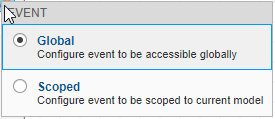
There are two options:
Global, ![]() – A global event indicates that an event is available for
use anywhere in the model hierarchy. You can use and connect the global event anywhere
within the model hierarchy. A global event is visible in the Events
panel for the parent model. A global event with, the name
– A global event indicates that an event is available for
use anywhere in the model hierarchy. You can use and connect the global event anywhere
within the model hierarchy. A global event is visible in the Events
panel for the parent model. A global event with, the name E1, that's
present in the model named ModelName.E1, is displayed as
E1 in the Events panel of the parent model. All
global events must have a unique name. You can use the global scope to combine multiple
instances of the same event. These multiple instances of the events can then be triggered
by the same Stateflow chart to unify scheduling.
Scoped,![]() – By default, the event is scoped, indicating that the
event is used within the context of the parent model. A scoped event is visible in the
Events panel for the parent model. A scoped event with the name
– By default, the event is scoped, indicating that the
event is used within the context of the parent model. A scoped event is visible in the
Events panel for the parent model. A scoped event with the name
E1, that's present in the model named ModelName,
is displayed as ModelName.E1 in the Events
panel.
Execution of Aperiodic Partitions with Events
Bind Events. An event and a partition can be bound together to indicate that the partition executes when the event is broadcast. A partition can be bound to multiple events.
To bind multiple events to a partition, hold the Shift key and drag the event on to the partition.
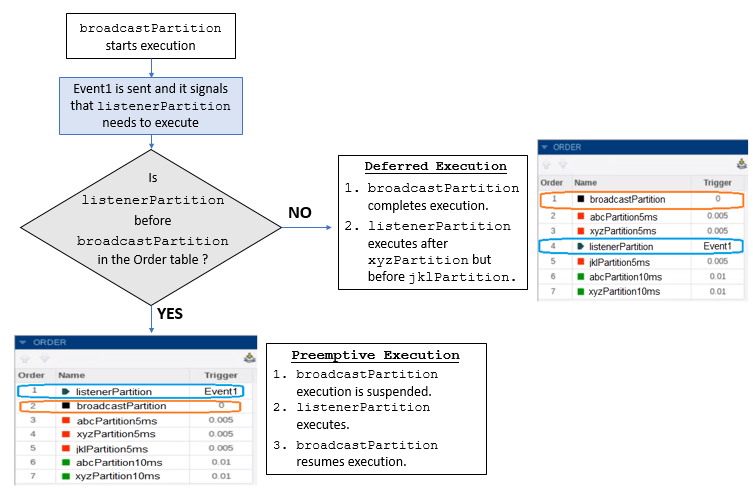
Priority Based Execution. If the event-bound partition is scheduled to run before the partition driving the event, then the event-bound partition execution preempts the execution of the partition driving the event. If the triggered partition is scheduled to run after the partition driving the event, then the triggered partition executes when the scheduler reaches its position in the execution order.
listenerPartition is an aperiodic partition and a listener to the
event, Event1. Suppose that Event1 comes from a
Stateflow Chart present in the model and is a part of the partition called,
broadcastPartition. When broadcastPartition
starts executing, Event1 occurs, which then triggers the execution of
listenerPartition.
Hit Times. You can trigger an aperiodic partition at specified hit times. If a partition has hit times and gets bound to an event, the hit times are replaced with the specified event. Likewise, if a partition is bound to an event and hit times are added, then the bound event is removed from the partition. Variables can also specify hit times for the aperiodic partitions. In case of ambiguous variable and events names, events are given precedence.
Schedule Partitions with Events
This example shows how you can use events to schedule the execution of aperiodic partitions via a Stateflow chart. You can send events from Stateflow and use those events to control the execution of the partitions in the model by using events in Schedule Editor.
Open the Model
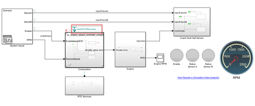
In this example, we simulate the digital speed control of an internal combustion engine. In this model, the angular velocity of the engine is measured using two redundant Hall sensors, and we simulate the failure of the Hall sensors.
The model primarily contains the following main components:
System Inputs: Inputs and signals to exercise the system.
Engine: Simplified representation of internal combustion engine.
Composition: Digital controller intended to deploy on an Engine Control Unit (ECU), with a Run-time Environment (RTE).
Crank Dual Hall Sensor: Emulation of two redundant sensors,
sensor Aandsensor B.RTE Services: Emulation of the services provided by Engine Control Unit.
open_system("ex_engine_speed_control_system");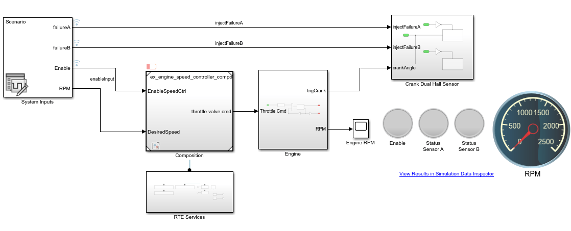
System Inputs
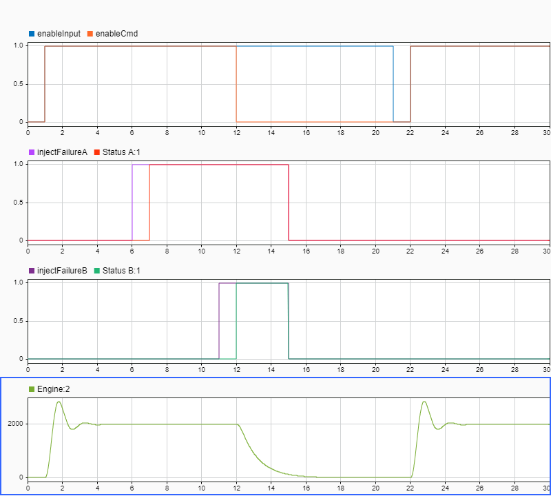
The system inputs for this model are designed using the Signal Editor block. The ex_engine_speed_control_external_inputs.mat file contains the following scenario:
The desired angular velocity is set to
2000 rpmfor the entire simulation.At
t = 01 sec, the speed controller is enabled. As a result,Hall sensor Ais being used to compute the angular velocity and the engine speed increases to2000 rpm.At
t = 06 sec, a failure of the first Hall sensor is injected. As a result,Hall sensor Bis now being used to compute the angular velocity, the engine speed remains at2000 rpm.At
t = 11 sec, a failure of the second sensor is injected. As a result, the speed controller is disabled, the engine speed falls toward zero.At
t = 15 sec, the failure ofsensors AandBgets resolved.At
t = 21 sec, the command to enable speed control is cycled back to zero for one second and back to one. As a result, the engine speed increases to2000 rpm.
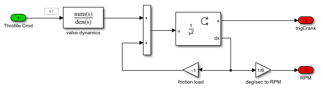
Engine
The engine dynamics are represented by a Transfer Function that receives a throttle command and converts it into torque, and a Second Order Integrator to integrate the motion.
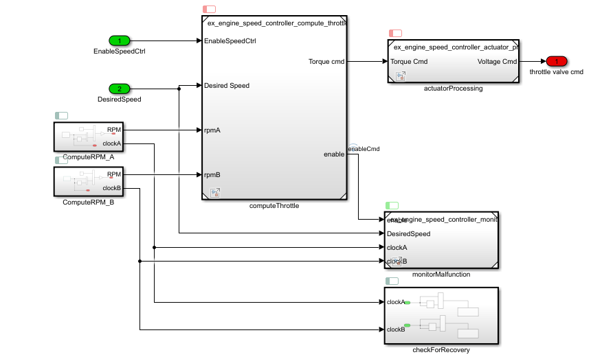
Composition
ex_engine_speed_controller_composition implements the digital control algorithm. It contains the following components:
ComputeRPM_AandComputeRPM_B****: Aperiodic partitions registered as hardware interrupts.Hall sensors AandBtrigger these partitions when the engine shaft rotates by every increment of 10 degrees.computeThrottleandactuatorProcessing****: Periodic partitions executing at 0.001 sec.computeThrottleinterrogates the RTE at every time step.monitorMalfunction****: Periodic partition executing at 0.01 sec. Monitors output signals ofComputeRPM_AandComputeRPM_Bto identify potential hardware failures. If a failure is detected, it calls a function provided by the RTE to register the failure.checkForRecovery****: Aperiodic partition that is triggered by RTE once a failure has been detected. Upon detection,checkForRecoveryis called by the RTE at a rate of 1 sec. It calls a function provided by the RTE if a recovery is detected.
Using the Schedule Editor, the events checkForRecovery, tringCrankA, and trigCrankB are created and bound to aperiodic partitions checkForRecovery, ComputeRPM_A, and ComputeRPM_B respectively. These events are broadcast from the top model.
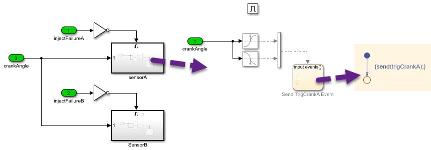
Crank Dual Hall Sensor
The Hall sensors are modeled using Hit Crossing blocks that generate a function-call every time the engine shaft rotates by increments of 10 degrees. When the Stateflow chart gets triggered, it sends events trigCrankA and trigCrankB, which have been bound to execute aperiodic partitions, ComputeRPM_A and ComputeRPM_B respectively.
RTE Services
The RTE Services subsystem emulates functionalities available on the Run-time Environment onto which the code generated form the digital controller is deployed. For simulation purposes, those services are emulated using Simulink Functions.
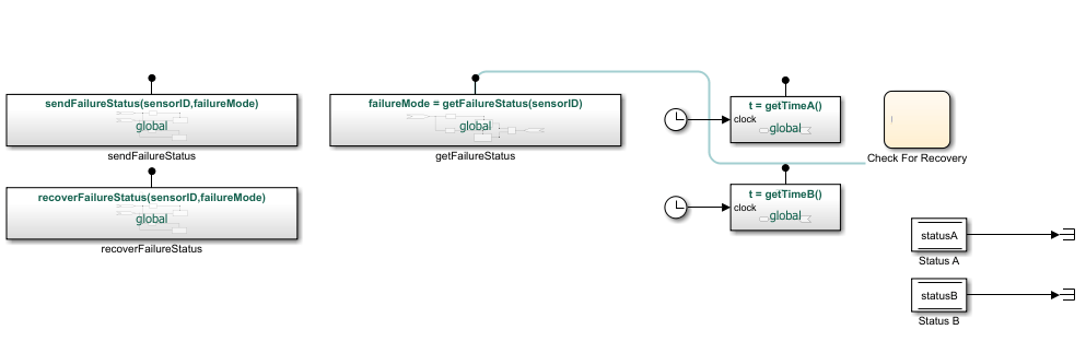
sendFailureStatusandrecoverFailureStatusare called respectively by themonitorMalfunctionsandcheckForRecoverypartitions when a failure or a recovery is detected. The global failure statuses are stored using Data Store Memory blocks for simulation purposes.getFailureModeis called by thecomputeThrottleto verify if a failure has been detected in one of the sensors.getTimeAandgetTimeBsimulate the RTE clock.Check for Recoverysimulates the logic to determine when thecheckForRecoveryaperiodic partition of the digital controller should be triggered. Triggering is done by broadcasting the eventcheckForRecovery.
Open the Schedule Editor
To open the Schedule Editor, on the Modeling tab in the Design Section, click Schedule Editor. Doing an Update Diagram compiles the models and shows you the existing partitions in the Schedule Editor.
Events Panel in the Schedule Editor
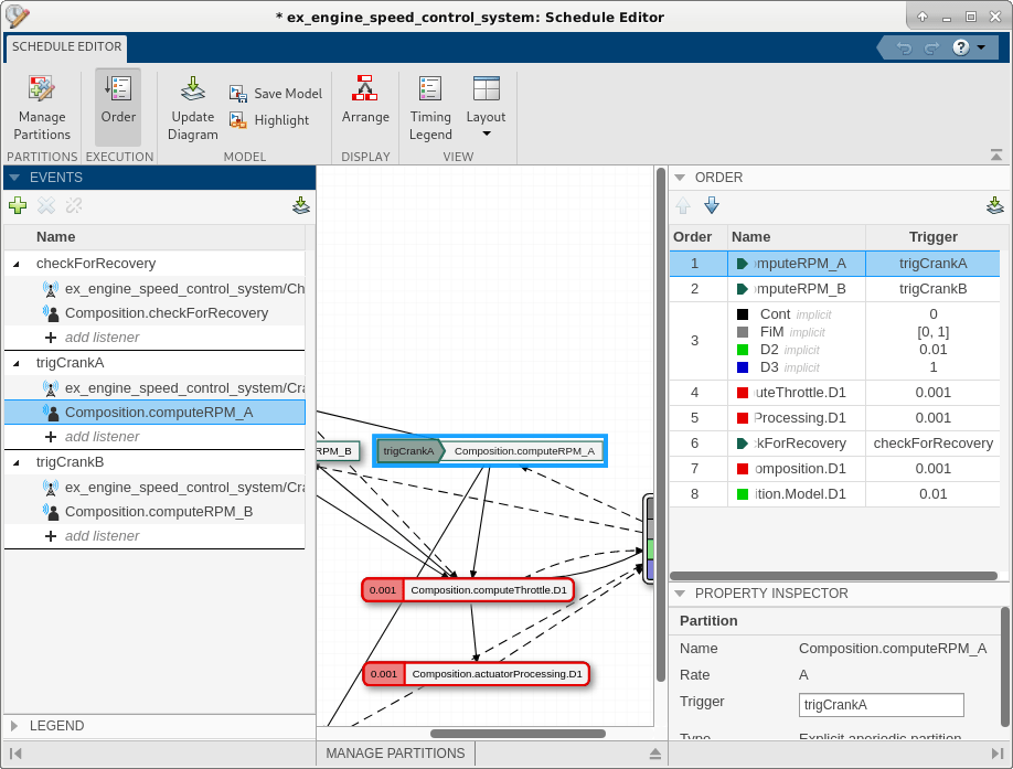
The events broadcast by the send keyword in Stateflow are shown in the Events panel of the Schedule Editor, these events are bound to aperiodic partitions, so that these partitions can be triggered from the top model. In the Events panel, you can expand each event to see the listeners and the broadcasters of that event. The icon, ![]() indicates broadcaster of the event and the icon,
indicates broadcaster of the event and the icon, ![]() indicates the listener. In this example, the sender of the event
indicates the listener. In this example, the sender of the event checkForRecovery is the Stateflow Chart in RTE Services subsystem, the sender of the events trigCrankA and trigCrankB is the Stateflow chart in the Crank Dual Hall -> Sensor A and Sensor B.
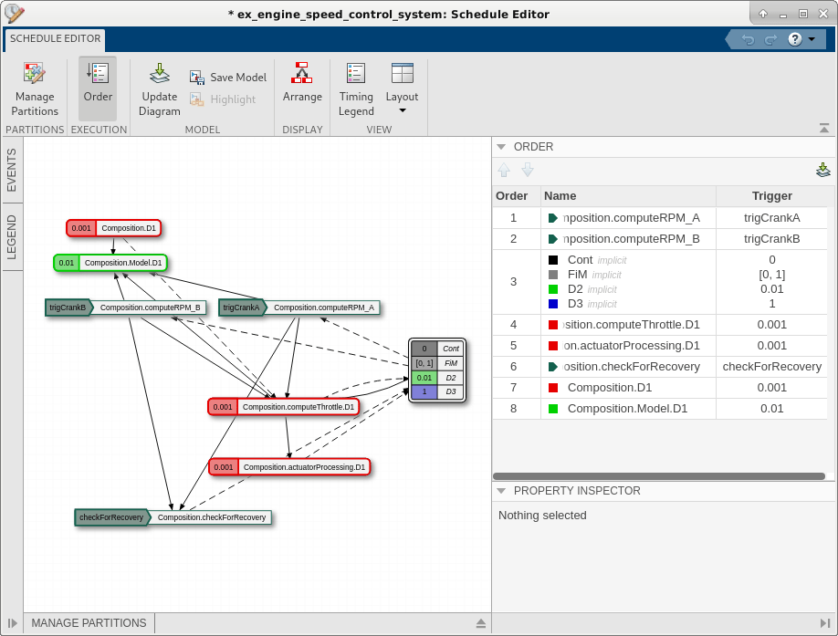
In the Order panel, the partitions are arranged in the order of priority of execution. Since ComputeRPM_A and ComputeRPM_B are time sensitive, their priority is the highest. Therefore, when the events trigCranA and trigCrankB are broadcast, the corresponding partitions ComputeRPM_A and ComputeRPM_B are executed immediately. In contrast, the aperiodic partition checkForRecovery is less time sensitive, and is lower in the priority order. Therefore, when the event checkForRecovery is broadcast, the execution of the corresponding partition checkForRecovery is deferred until all the partitions with higher priority complete execution.
You can view this event connection in the Simulink® model, this connection conveys the flow of execution between a block broadcasting an event and another block listening to that event. To view this connection, on the Simulink Toolstrip, on the Debug tab, select Information Overlays in the Diagnostic section. From the drop-down menu, select Connectors in the Blocks section. Select the Schedule Connectors option from the Connectors pane that appears on the Simulink canvas.
Simulation Results
Click on View Results in Simulation Data Inspector in the model to view the results of the simulation.
Test Harness Generation
You can use the Schedule Editor to generate a test harness for a model with events. Using events with test harnesses helps you avoid complex wiring between the test sequence block and the entire system.
The generated test harness gets its own Schedule Editor, which enables you to easily send events through the test harness. Through the test harness scheduler, you can test the model under different scenarios by triggering events at specific times.
The Events panel also allows you to bind existing events to other aperiodic partitions. You can do this by dragging and dropping the event over a valid aperiodic partition, or by adding the partition directly using the dropdown. You can order the partitions that have events as their Trigger in the Order table relative to the other partitions. You can also create events in Schedule Editor. Click the plus icon. Double click Add Row to create a new event. You can use this event to send from Stateflow to schedule execution of an aperiodic partition.
Limitations and Error Conditions
Events in the Schedule Editor cannot be used in models with export-functions.
Events do not support code generation and do not impact the generated code.
Events in the Schedule Editor use the following guidelines:
An event cannot be sent before that event has processed.
Duplicate event names in the parent model caused by giving two model references the same name are not allowed.
Infinite looping is not allowed.
A partition cannot send an event that triggers itself.