Implement Task Parallelism in Simulink
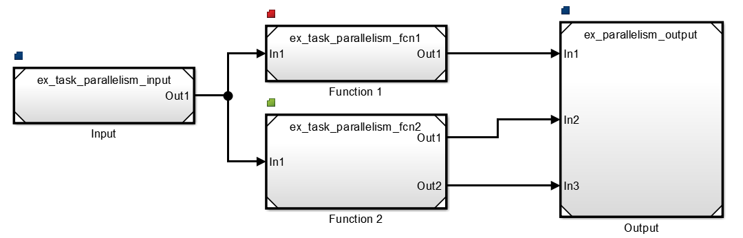
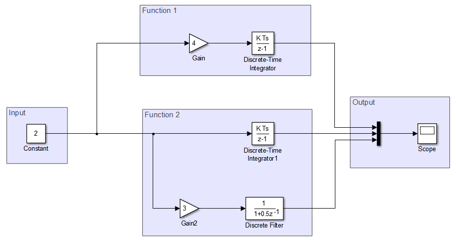
This example shows how to implement task parallelism for a system represented in a Simulink® model. The ex_task_parallelism_initial model consists of an input, functional components applied to the same input, and a concatenated output. For more information on task parallelism, see Types of Parallelism.
Set this model for concurrent execution. To see the completed model, open the ex_task_parallelism_top model.
Configure Model for Concurrent Execution
Open the
ex_task_parallelism_initialmodel.Convert areas in this model to referenced models. Use the same referenced model to replace each of the functional components that process the input.
Set Model Configuration Parameters
Click Configure Tasks. In the Concurrent Execution dialog box, in the right pane, select the Enable explicit model partitioning for concurrent behavior check box. With explicit partitioning, you can partition your model manually.
On the Modeling tab, click Model Settings.
Select Solver, set Type to
Fixed-step, and click Apply.On the Solver pane, expand Solver details. Check that Periodic sample time constraint is set to
Unconstrained. Under Tasking and sample time options, select Allow tasks to execute concurrently on target.Select Code Generation > Interface > Advanced parameters. Clear the MAT-file logging check box.
Partition Model Using Explicit Partitioning
Partition the top model.
In the Concurrent Execution tree, under Tasks and Mapping, select CPU. Click Add task three times to add three new tasks.
Map Blocks to Tasks
In the Concurrent Execution tree, select Tasks and Mapping. On the Map block to tasks pane:
Under Block: Input, click
select taskand selectPeriodic: Task.Under Block: Function 1, select
Periodic: Task1.Under Block: Function 2, select
Periodic: Task2.Under Block: Output, select
Periodic: Task.
The Input and Output model blocks are on one task. Each functional component is assigned a separate task.
In the Concurrent Execution tree, select Data Transfer. In the Data Transfer Options pane, set the parameter Periodic signals to Ensure deterministic transfer (minimum delay). Click Apply and close the Concurrent Execution dialog box.
Finalize Model
Share Configuration Parameters with Referenced Models
Apply configuration parameters to all referenced models.
Initialize Data Dictionary to Store Configuration Set
Create a
Simulink.data.dictionary.Entryobject that represents the configuration set, which is an entry in the dictionary. For this example, suppose the name of the dictionary ismyData.slddand the name of theSimulink.ConfigSetobject ismyConfigs.Store a copy of the target
Simulink.ConfigSetobject in a temporary variable.Save changes made to the dictionary.
Create a freestanding configuration set in the base workspace by copying the active configuration set of the model.
Create a separate configuration reference for the top model and each reference model. To point the reference to your freestanding configuration, set the
SourceNameproperty tofreeConfigSet, the variable that represents your configuration.Attach the configuration reference to each model by using the
ConfigSetRefobject. To use the configuration reference in the model, activate it for each model.
For more information, see Share a Configuration with Multiple Models, Automate Model Configuration by Using a Script, and Make Changes to Configuration Set Stored in Dictionary.
Update your model to see the tasks mapped to individual model blocks.