Plot Array on Android Device
This example shows how to create an Android® app to plot vector or array data on an Android device using the Array Plot block of DSP System Toolbox™ through a Simulink® model. To implement this workflow, you must install the Simulink Support Package for Android Devices.
Introduction
Android devices provide a user interface to visualize signals or display data on device screen. By using Array Plot (DSP System Toolbox) block, you can display signals generated during simulation in real-time.
By displaying the Array Plot on an Android device screen, you can:
Visualize vector or array data in real-time directly on your Android device screen.
View signals without a connection to your development computer.
Customize the Array Plot style to suit your app.
This example provides two Simulink models:
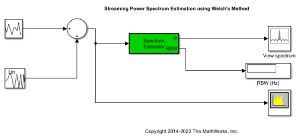
dspstreamingwelch— This model displays the power spectrum estimate of a streaming time-domain input via Welch's method of averaged modified periodograms. This model runs on the development computer. For more information on this model, see Streaming Power Spectrum Estimation Using Welch's Method (DSP System Toolbox).
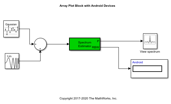
androidarrayplot— Showcases how the power spectrum estimate is displayed on the Android device using an Array Plot.
Prerequisites
Required Hardware
Android device
USB cable to connect the device to your development computer
Task 1 - Display Signals on the Development Computer
The Spectrum Estimator block in dspstreamingwelch model estimates the spectrum of a noisy chirp signal, sampled at 44100 Hz. The Array Plot block displays the power spectrum estimate.
1. Open the dspstreamingwelch Simulink model.


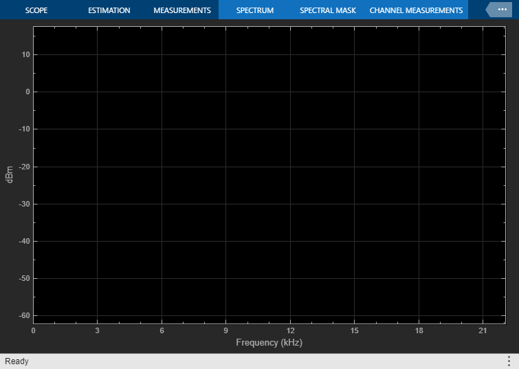
2. Double-click the Array Plot block to open the Array Plot window.
3. In the Simulink model, select the Simulation tab and click Run to see the output of the streaming power spectrum estimate.

Task 2 - Display Signals on Your Android Device
Display the power spectrum estimate on your Android device.
1. Open the androidarrayplot Simulink model.

2. Note how the Simulink Display block has been replaced with a Data Display block from the Android Support Package. This allows you to view the resolution bandwidth (RBW) on your Android Device.
3. On the Modeling tab of the toolstrip, select Model Settings.
4. Select the Hardware Implementation pane and from the Hardware board parameter list, and confirm it is set to Android Device.
5. Click Device options and ensure that the device matches your device setting. Click OK.
6. On the Hardware tab of the Simulink model, in the Mode section, select Run on board and then click Build, Deploy & Start to run the Simulink model on your device. In the current working directory, a folder named "androidarrayplot_ert_rtw" contains all the model's generated project files.

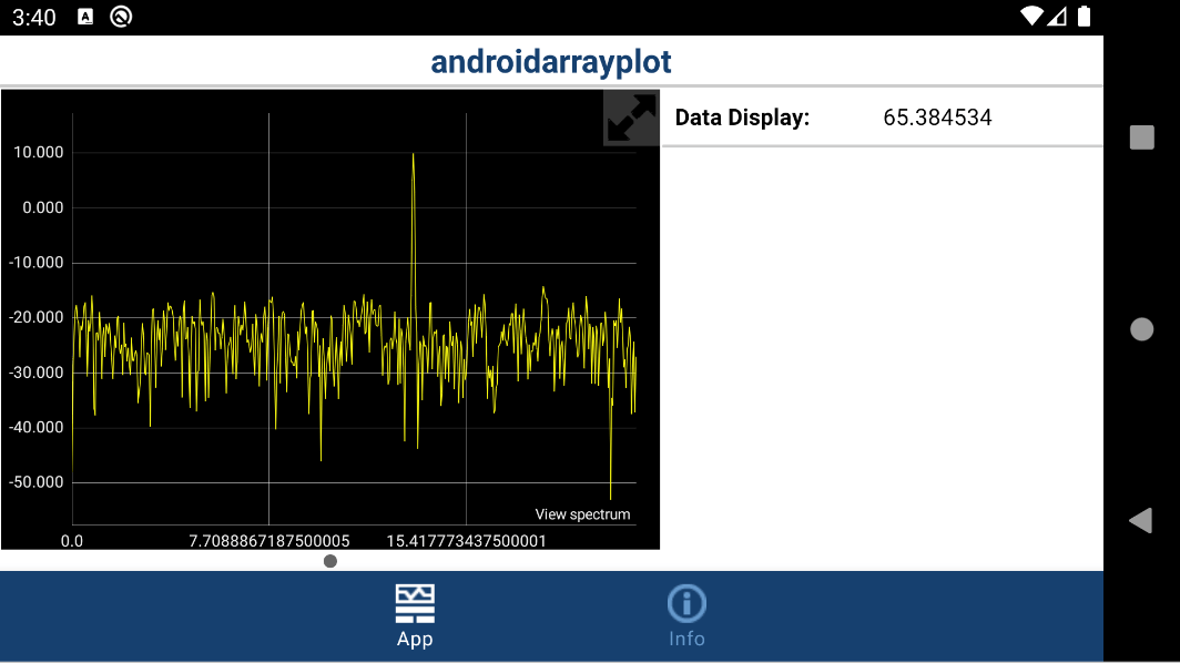
The app displays the power spectrum estimate on your device.
Task 3 - Customize Array Plot Style on Your Android Device
Using the model from Task 2, configure the appearance and style of the Array Plot displayed on your Android device.
1. Open the androidarrayplot Simulink model.
2. Double-click the Array Plot block to open the Scope window.
3. In the Scope menu, click View > Style to open the Style dialog.
3. Set the Figure color to gray.
4. Modify the Axes colors. Set the Axes background color to white. Set the Ticks, labels, and grid colors to gray.
5. Set Plot type to Stem.
6. Click OK.
7. To see the style changes reflected in the app, you must remove the previous project. In the MATLAB® Command Window, run:
rmdir('androidarrayplot_ert_rtw', 's');
8. To update these style changes on the Android device, you must re-build and download the changes by clicking on the Build, Deploy & Start button of the Simulink model.

The Array Plot in the app reflects the new line and axes properties from the Style dialog box of the Array Plot block.
Other Things to Try
Modify the model to display signals from Android Device sensors.
Change the scope style to suit your app.