Use Fixed-Step Zero-Crossing Detection for Faster Simulations
This example shows how fixed-step zero-crossing detection can be used to speed up simulation by increasing the fixed-step size without sacrificing simulation accuracy. Zero-crossing detection is essential if a system contains events that will change the equations in the system. The location and reaction to these events is important for accurate simulation.
Load Model
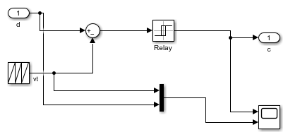
This example uses a model of a buck converter, a DC-DC power converter. The converter is controlled via pulse width modulation (PWM), where a switch, represented by the Relay block in the PWM subsystem, is controlled by comparing the control voltage to a triangular voltage.
This model implements an open-loop version of the buck converter.
model = 'buck_ol';
open_system(model);

Examine PWM Generation System
The buck converter in this model uses PWM to control the power transmitted to the load. The Relay block in the PWM subsystem represents a switch and is controlled by comparing the control voltage to a triangular voltage. The frequency of the triangle wave is 100 kHz. To accurately detect PWM switching, check that the solver takes steps smaller than 1.0e-5. The relay block in a PWM system detects zero crossings when the triangle wave intersects with the duty cycle.
pwmGenSubsys = [model '/PWM'];
open_system(pwmGenSubsys);
Simulate with a Variable-Step Solver
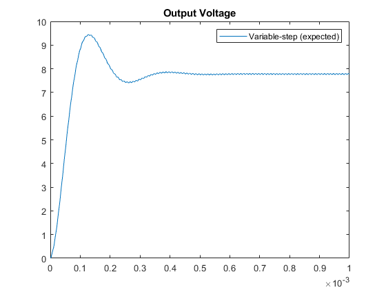
To achieve accurate simulation results, you must accurately locate the switching times that occur in the PWM subsystem. To see what the results should look like, you can first simulate the model using a variable-step solver with zero-crossing detection. Limit the max-step size of the solver to 1e-6 to ensure that you do not miss PWM switching events.
set_param(model, 'Solver', 'ode45', 'MaxStep', '1e-6',...
    'ReturnWorkspaceOutputs', 'on')
simout = sim(model);
plot(simout.tout, simout.xout(:,1));
title('Output Voltage');
legend('Variable-step (expected)');
xlim([0 1e-3]);
Use Fixed-Step Simulation
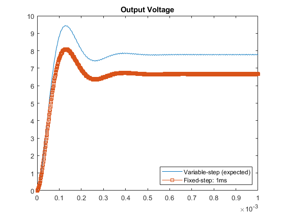
Now that you know what the expected simulation results should look like, you can simulate the model using a fixed-step solver. You should select the largest possible fixed-step size where the solver is still able to step near the PWM switching times. Using a large fixed-step size will result in the fastest possible simulation while still obtaining accurate results.
Use the simulation results generated by the variable-step solver to inform your choice for a fixed-step size. Start by using a fixed-step size of 1.0e-6, similar to the maximum step size used for the variable-step simulation.
set_param(model, 'Solver', 'ode3', 'FixedStep', '1.0e-6');
set_param(model, 'EnableFixedStepZeroCrossing', 'off')

simout_FS_1ms = sim(model);

plot(simout.tout, simout.xout(:,1), ...
    simout_FS_1ms.tout, simout_FS_1ms.xout(:,1), '-s');
title('Output Voltage');
legend('Variable-step (expected)', 'Fixed-step: 1ms',...
    'Location', 'southeast');
xlim([0 1e-3]);
Reduce Fixed-Step Size
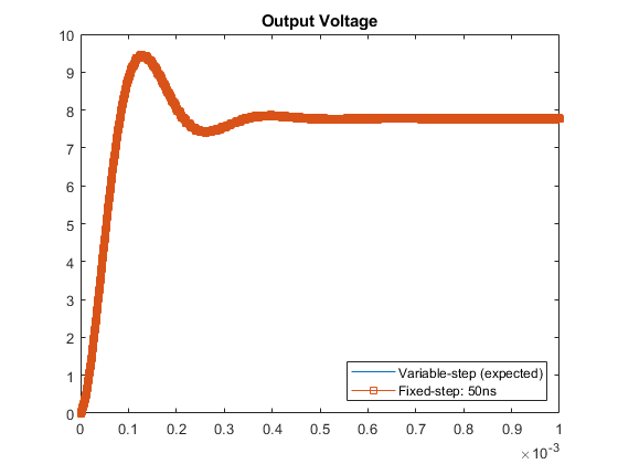
This plot shows that the results obtained with a fixed-step size of 1.0e-6 are not very accurate when compared to the variable-step baseline. Reducing the step size to 5.0e-8 produces more accurate results. Without zero-crossing detection, 5.0e-8 is the largest fixed-step size you can use for this model while still obtaining accurate simulation results.
set_param(model,'FixedStep', '5.0e-8');
simout_FS_50ns = sim(model);

plot(simout.tout, simout.xout(:,1), ...
    simout_FS_50ns.tout, simout_FS_50ns.xout(:,1), '-s');
title('Output Voltage')
legend('Variable-step (expected)', 'Fixed-step: 50ns',...
    'Location', 'southeast')
xlim([0 1e-3]);
Enable Zero-Crossing Detection for fixed-step simulation
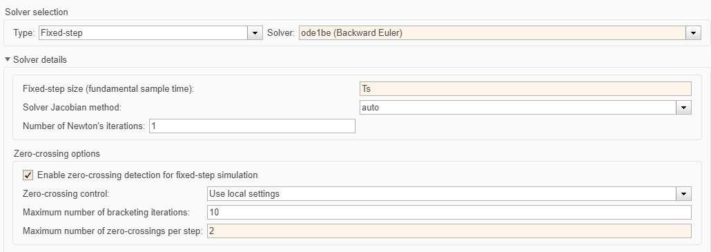
Open up the solver pane of the configuration parameters and select Enable zero-crossing detection for fixed-step simulation. Enabling this parameter allows Simulink® to detect zero crossings between major time steps and apply corrections to continuous states in the model. Use the default value for Maximum number of zero-crossings per step.
set_param(model, 'EnableFixedStepZeroCrossing', 'on')
set_param(model, 'FixedStep', '1.0e-6', 'MaxZcPerStep', '2');
simout_FSZC_1ms = sim(model);
Compare Results
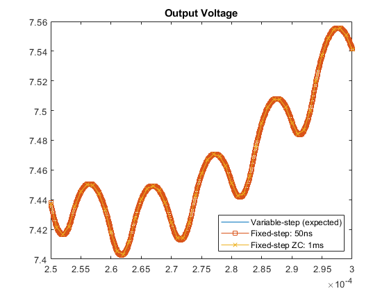
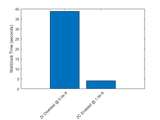
With zero-crossing detection enabled for fixed-step simulation, you can use a step size that is twenty times larger than the fixed step size used without zero-crossing detection and still obtain accurate results. This larger step size leads to faster simulation times.
figure()
state = 1;
plot(simout.tout, simout.xout(:,state), ...
    simout_FS_50ns.tout, simout_FS_50ns.xout(:,state),'-s' , ...
    simout_FSZC_1ms.tout, simout_FSZC_1ms.xout(:,state), '-x');
title('Output Voltage')
legend('Variable-step (expected)', 'Fixed-step: 50ns','Fixed-step ZC: 1ms',...
    'Location', 'southeast')
xlim([0 1e-3]);
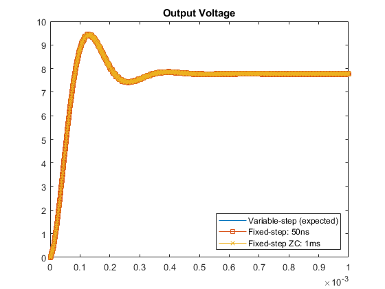
Zoom in to see that the results are accurate with zero crossing detection enabled, even with this larger step size.
xlim([2.5e-4 3e-4])
ylim([7.4 7.56])
Finally, note that the simulation time is faster at this larger step size with zero-crossing detection enabled.
bar([simout_FS_50ns.SimulationMetadata.TimingInfo.ExecutionElapsedWallTime,...
    simout_FSZC_1ms.SimulationMetadata.TimingInfo.ExecutionElapsedWallTime])
xticklabels(gca, {'Zc Disabled @ 5.0e-8', 'ZC Enabled @ 1.0e-6'});
xtickangle(45);
ylabel("Wallclock Time (seconds)")
See Also
Enable zero-crossing detection for fixed-step simulation | Maximum number of zero-crossings per step | Number of consecutive zero crossings