Create a Realistic Dashboard Using Blocks from the Customizable Blocks Library
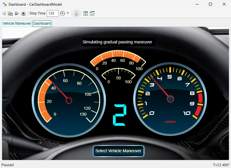
Using blocks from the Customizable Blocks library, you can create a dashboard of displays and controls for your model that looks like a real system. This example uses a dashboard panel to create a dashboard for the sf_car model like one you might see in a real car. The displays on the dashboard are modeled using Circular Gauge blocks and Display blocks.
For information about panels, see Getting Started with Dashboard Panels.
Simulate Vehicle Maneuvers
The panel has two tabs, the Vehicle Maneuver tab and the Dashboard tab. On the Vehicle Maneuver tab, you can select which vehicle maneuver to simulate. The Dashboard tab contains the car dashboard. By default, the panel displays the Vehicle Manuever tab.
The sf_car model can simulate four vehicle maneuvers:
Coasting
Gradual acceleration
Hard braking
Passing maneuver
The Vehicle Maneuver tab has four buttons, one for each available vehicle maneuver. To simulate a vehicle maneuver, click the corresponding button.

When you click the button, the panel switches to display the Dashboard tab containing the car dashboard. Watch the gauge needles move and the gear numbers change as the software simulates the selected vehicle maneuver.
To select a different vehicle maneuver, click the button with the label Select Vehicle Maneuver. The button stops the simulation and displays the Vehicle Maneuver tab.
To switch tabs without stopping the simulation, in the upper left of the window showing the panel, click the tab name. If you switch to the Vehicle Maneuver tab during simulation, stop the simulation or wait for the simulation to finish before you select a new vehicle maneuver.
Explore Dashboard
Switch to the Dashboard tab.
With the exception of the button, the blocks in the Dashboard tab are display blocks, meaning they display the values of the signals to which they are connected. You can explore the relationship between the dashboard and the model by jumping from any display block to the connected signal. To do so, the panel must be unlocked. By default, when a panel is open in its own window, the panel is locked. In the toolstrip of the panel window, click the Unlock Panel button.

Position the model and panel windows such that you can see both simultaneously. Select a block on the dashboard. Pause on the ellipsis (...) that appears. In the action bar that expands, click Jump to Connected Element. The model navigates to where the connected signal exists and briefly highlights the signal. Repeat these steps for the other blocks to see how they connect to the model.

The Circular Gauge block on the left side of the Dashboard tab displays the Vehicle Speed signal, acting as a speedometer on the dashboard. The appearance of the block is customized. The scale limits, tick interval, and tick height have been changed from those of the default Circular Gauge block. When you simulate the model, an orange value bar helps indicate the gauge value.
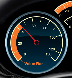
To create this gauge, add a Circular Gauge block from the Customizable Blocks library to your model and enter design mode. To enter design mode, select the block, pause on the ellipsis that appears over the block, and in the action bar that expands, click Edit Custom Block. In the toolbar that appears, click Open Design Tab. In the Property Inspector, on the Design tab, adjust the scale limits, tick interval, tick height, and value bar color. When you finish, exit design mode by clicking the X in the upper right corner of the canvas. To check your work, open CarDashboardModel.slx, select the speedometer, open the Design Tab of the Property Inspector, and compare the parameter values with those of the block you created. For more information about how to customize Circular Gauge blocks, see Circular Gauge.
The Circular Gauge blocks at the top of the model display the Throttle and Brake signals. To create these gauges, add two Circular Gauge blocks to your model. For each, enter design mode, and on the Design tab of the Property Inspector, delete the background image and needle image. Then, adjust the scale arc, scale limits, and value bar color. When you finish, exit design mode.

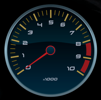
The Circular Gauge block on the right displays the Engine RPM signal on a custom gauge face. To create a gauge like this one, add a Circular Gauge block to your model, and enter design mode. On the Design tab of the Property Inspector, delete the background image and upload automotive-dashboard-tachometer-gauge-background.png or your own image. When you finish, exit design mode.
The Display block at the bottom of the dashboard displays the Gear signal using seven segment numbers. To create this display, add a Display block from the Customizable Blocks library to your model. Enter design mode. On the Design tab of the Property Inspector, switch to using a custom background color instead of a background image. Select the display font DSEG7 Classic, the font size 72, the font color turquoise, and the font style bold. When you finish, exit design mode. For more information about how to customize a Display block, see Display.

The Display block at the top of the dashboard displays which vehicle maneuver is being simulated. The block connects to the Maneuver signal. To create this display, add a Display block from the Customizable Blocks library to your model. Enter design mode. On the Design tab of the Property Inspector, switch to using a custom background color instead of a background image. Select the display font Roboto, the font size 14, and the font color gray. When you finish, exit design mode.
The Callback Button block at the bottom of the dashboard stops the simulation and switches to the Vehicle Maneuver tab. Callback Button blocks do not connect to other blocks. To create this button, add a Callback Button block from the Customizable Blocks library to your model. Enter design mode. On the Design tab of the Property Inspector, change the button text to Select Vehicle Maneuver. On the Parameters tab of the Property Inspector, enter these commands. The first command stops the simulation. The second command switches to the Vehicle Maneuver tab using the simulink.dashboard.switchPanelTab function.
set_param(mdl,SimulationCommand="stop");
simulink.dashboard.switchPanelTab(mdl,"Vehicle Maneuver");
For more information about how to customize a Callback block, see Callback Button.
Try creating the blocks. Then, connect the blocks, promote the blocks to a panel, and change the panel background to look like a real car dashboard.
To connect a dashboard block to a signal, select or pause your pointer on the block. Click the Connect button above the block. Click the signal line. Select the signal to which you want to connect the block. Click the Done Connecting button above the block. For information about connecting dashboard blocks, see Connect Dashboard Blocks to Simulink Model.
To promote blocks you create to a panel, select the blocks. Pause on the ellipsis that appears. In the action bar that expands, click Promote to Panel.

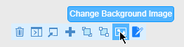
To give the panel a custom background, select the panel. Pause on the ellipsis that appears. In the action bar that expands, click Edit Panel. The action bar options change. In action bar, click Change Background Image. Select automotive-dashboard-panel-background.png, or your own image. Then, in the action bar, click Done Editing.
To move the panel into a separate window, select the panel. Pause on the ellipsis that appears. In the action bar that expands, click Open in New Window.
