Create Harness-Free Models with MAT File Input Data
This example shows how to map MAT file data to the root-level input ports, which creates a harness-free model. Using root-level input ports can speed up simulation time. In the example, you convert a model with a Signal Editor input block to a harness-free model with root-level input ports. The harness-free model uses the data from the Signal Editor block MAT file.
Open Example Model
Open the sldemo_autotrans model.
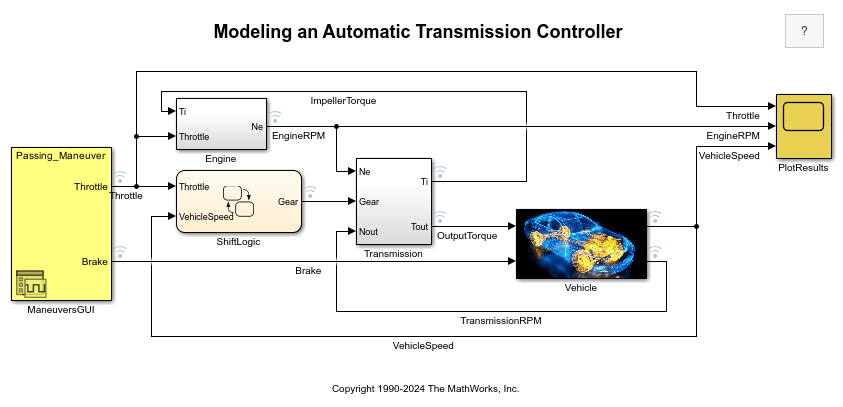
Remove Signal Editor Block
Replace the Signal Editor block named ManeuversGUI with two input ports.
Delete the Signal Editor block named
ManeuversGUI.From the Simulink/Commonly Used Blocks library, drag two Inport blocks into the model.
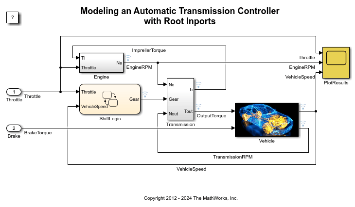
Connect the input ports to the lines previously connected to the Signal Editor block.
Rename the input ports. Name the input port connected to the
Throttlesignal Throttle. Name the input port connected to theBrakeTorquesignal Brake.
Save the model as slexAutotransRootInportsExample1 or slexAutotransRootInportsExample.
The remaining steps of this example use the model slexAutotransRootInportsExample. If you saved the model with a different name, use your model name.
Set Up Harness-Free Inputs
Now that the model is harness-free, set up the inputs from the MAT file previously used by the Signal Editor block.
In the Modeling tab, click Model Settings. In the Data Import/Export pane, click Connect Inputs.
Map Signals to Root Inport
The Root Inport Mapper tool opens.
The example uses this tool to set up the model inputs from the MAT file and map those inputs to an input port, based on a mapping algorithm. To select the MAT file that contains the input data, on the Root Inport Mapper toolbar, click From MAT-File. When the link dialog box appears, click the Browse button. In the browser, select the MAT file from the local working example folder. For this example, the file name is VehicleManeuvers.mat.
![]()
Select Map Mode
When you select the MAT file VehicleManeuvers.mat, determine the root input port to which to send input data. Simulink® matches input data with input ports based on one of five Map Mode criteria:
Port Order — Maps in the order it appears in the file to the corresponding port number.
Block Name — Maps by variable name to the corresponding root input port with the matching block name.
Signal Name — Maps by variable name to the corresponding root input port with the matching signal name.
Block Path — Maps by the BlockPath parameter to the corresponding root input port with the matching block path.
Custom — Maps using a MATLAB® function.
The selected MAT file has input data with variables of the same name as the harness signals Throttle and Brake, and input ports with names matching the variables. Given the set of conditions for the input data and the model input ports, the best choice for a mapping criterion is Block Name. Using this criterion, Simulink tries to match input data variable names to the names of the input ports. To select this option:
In the Map Mode list, click Block Name.
Click Options and select Update Model Automatically. This option verifies the mapping.
Click Check Map Readiness.
When compiling the data, Simulink evaluates input ports against the following criteria to determine compatibility issues. The status of this compatibility is reflected by the table colors green, orange, or red. Warnings and errors are flagged with diagnostic messages. If the Options > Update Model Automatically option is not selected, the Root Inport Mapper tool determines the compatibility status by evaluating these block parameters and assigned signals:
Data Type — Double, single, enum, ....
Complexity — Real or complex
Dimensions — Signal dimensions versus port dimensions
![]()
Finalize Inputs to Model
Review the results of the mapping compatibility. In the Scenario Dataset list, select Passing_Maneuver. To prepare for simulation, click Apply to Model. This action applies the mapping variables to the Configuration Parameter Data Import/Export > External Input text box. If this text box has content, the content is overwritten.
Simulate Model
With the changes applied, you can now simulate the model. To view the results of the simulation, double-click the PlotResults scope block.
![]()
See Also
getRootInportMap | getSlRootInportMap