Main Content

PS Ramp

Generate constantly increasing or decreasing physical signal

Since R2021a

  • PS Ramp block

Libraries:
Simscape / Foundation Library / Physical Signals / Sources

Description

The PS Ramp block generates a physical signal that remains at a specified initial value and then, starting at a specified time, changes by a specified rate. The Slope, Start time, and Initial output parameters determine the characteristics of the output signal:

  • The Initial output and Slope parameter values determine whether the output signal is a scalar, vector, or matrix. If one of them is a vector or a matrix, the other must be a vector or a matrix of the same size, or a scalar. The output signal is then also a vector or a matrix of the same size.

  • The unit of Initial output determines the output signal unit.

  • The unit of Slope multiplied by unit of time must be commensurate with the unit of Initial output.

The output remains at the Initial output until the Start time, then increases or decreases based on the Slope:

  • Positive Slope values indicate the increase rate.

  • Negative Slope values indicate the decrease rate.

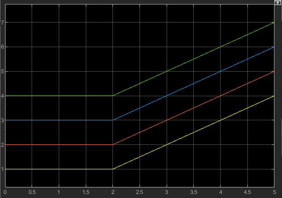
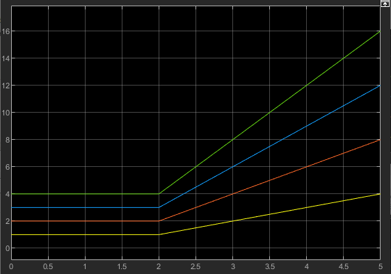
The table shows examples of block output for various combinations of scalar and nonscalar block parameter values.

Block ParametersOutput

Slope [1 2; 3 4] m/s

Start time 2 s

Initial input 1 m

Plot of signal output values

Slope 1 m/s

Start time 2 s

Initial input [1 2; 3 4] m

Plot of signal output values

Slope [1 2; 3 4] m/s

Start time 2 s

Initial input [1 2; 3 4] m

Plot of signal output values

Ports

Output

expand all

Output physical signal. The signal unit is determined by the unit of the Initial output parameter. The signal size matches the size of Initial output and Slope parameter values.

The port name is not visible in the block icon, but you can see this name in the underlying source file by clicking the Source code link in the Description tab of the block dialog box.

Parameters

expand all

The increase or decrease rate of the output signal at port O. The first edit box represents the signal increase or decrease rate value. You can specify a scalar, vector, or matrix. By default, the value is a scalar, 1. If you specify a vector or a matrix, Initial output must also be a vector or a matrix of the same size, or a scalar.

You can specify both positive and negative values. Positive values indicate the increase rate, and negative values indicate the decrease rate.

The second combo box represents the unit. By default, the unit is 1/s. The drop-down list contains a standard set of units. You can select a unit, or type the desired unit name, such as rpm, or a valid expression, such as m^2/s. For more information and a list of unit abbreviations, see How to Specify Units in Block Dialogs and Unit Definitions. The specified unit, when multiplied by unit of time, must be commensurate with the unit of the Initial output parameter.

The time when the signal increase or decrease begins. Between the start of simulation and Start time, the output of the block remains at the Initial output value.

The value and unit of the output signal at port O at the start of simulation. The first edit box represents the signal value. You can specify a scalar, vector, or matrix. By default, the value is a scalar, 0. If you specify a vector or a matrix, Slope must also be a vector or a matrix of the same size, or a scalar.

The second combo box represents the unit of the output signal. By default, the unit is 1 (unitless). The drop-down list contains a standard set of units. You can select a unit, or type the desired unit name, such as Pa, or a valid expression, such as m^2. For more information and a list of unit abbreviations, see How to Specify Units in Block Dialogs and Unit Definitions.

Extended Capabilities

C/C++ Code Generation
Generate C and C++ code using Simulink® Coder™.

Version History

Introduced in R2021a