Local Restriction (MA)
Restriction in flow area in moist air network

Libraries:
Simscape /
Foundation Library /
Moist Air /
Elements
Description
The Local Restriction (MA) block models the pressure drop due to a localized reduction in flow area, such as a valve or an orifice, in a moist air network. Choking occurs when the restriction reaches the sonic condition.
Ports A and B represent the restriction inlet and outlet. The input physical signal at port AR specifies the restriction area. Alternatively, you can specify a fixed restriction area as a block parameter.
The block icon changes depending on the value of the Restriction type parameter.
| Restriction Type | Block Icon |
|---|---|
|
|
|
|

The restriction is adiabatic. It does not exchange heat with the environment.
The restriction consists of a contraction followed by a sudden expansion in flow area. The moist air accelerates during the contraction, causing the pressure to drop. The moist air separates from the wall during the sudden expansion, causing the pressure to recover only partially due to the loss of momentum.
Local Restriction Schematic
Caution
Moist air flow through this block can choke. If a Mass Flow Rate Source (MA) block or a Controlled Mass Flow Rate Source (MA) block connected to the Local Restriction (MA) block specifies a greater mass flow rate than the possible choked mass flow rate, the simulation generates an error. For more information, see Choked Flow.
The block equations use these symbols.
| Mass flow rate | |
| Φ | Energy flow rate |
| p | Pressure |
| ρ | Density |
| R | Specific gas constant |
| S | Cross-sectional area |
| Cd | Discharge coefficient |
| h | Specific enthalpy |
| cp | Specific heat at constant pressure |
| T | Temperature |
Subscripts a, w, d, and
g indicate the properties of dry air, water vapor, water
droplets, and trace gas, respectively. Subscripts lam and
tur indicate the laminar and turbulent regime, respectively.
Subscripts A and B indicate the appropriate port.
Subscript R indicates the restriction.
Mass balance:
Energy balance:
When the flow is not choked, the mixture mass flow rate (positive from port A to port B) in the turbulent regime is
Subscripts in and out indicate the inlet and
outlet, respectively. If pA ≥
pB, the inlet is port
A and the outlet is port B; otherwise,
they are reversed. The cross-sectional area S is assumed to be equal
at ports A and B.
SR is the area at the restriction.
The mixture mass flow rate equation is derived by combining the equations from two control volume analyses:
Momentum balance for flow area contraction from the inlet to the restriction
Momentum balance for sudden flow area expansion from the restriction to the outlet
In the analysis for the flow area contraction, pressure pin acts on the area at the inlet, S, and pressure pR acts on the area at the restriction, SR. The pressure acting on the area outside the restriction, S − SR, is assumed to be (pinS + pRSR)/(S + SR).
In the analysis for the flow area expansion, the pressure acting on both the area at the restriction, SR, and the area outside the restriction, S − SR, is assumed to be pR, because of flow separation from the restriction. The pressure acting on the area at the outlet , S, is equal to pout.
The mixture mass flow rate (positive from port A to port B) in the laminar regime is linearized with respect to the pressure difference:
where the threshold for transition between the laminar and turbulent regime is defined based on the laminar flow pressure ratio, Blam, as
When , the flow is assumed to be turbulent and therefore .
When , smoothly transitions to .
When the flow is choked, the velocity at the restriction is equal to the speed of sound and cannot increase any further. Assuming the flow is choked, the mixture mass flow rate is
where . Therefore, the actual mixture mass flow rate is equal to , but is limited in magnitude by :
The expression for the pressure at the restriction is obtained by considering the momentum balance for flow area contraction from the inlet to the restriction only.
The local restriction is assumed adiabatic, so the mixture specific total enthalpies are equal. Therefore, the changes in mixture specific enthalpies are:
Assumptions and Limitations
The restriction is adiabatic. It does not exchange heat with the environment.
This block does not model supersonic flow.
Examples
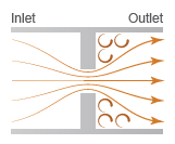
Vehicle HVAC System
Models moist air flow in a vehicle heating, ventilation, and air conditioning (HVAC) system. The vehicle cabin is represented as a volume of moist air exchanging heat with the external environment. The moist air flows through a recirculation flap, a blower, an evaporator, a blend door, and a heater before returning to the cabin. The recirculation flap selects flow intake from the cabin or from the external environment. The blender door diverts flow around the heater to control the temperature.
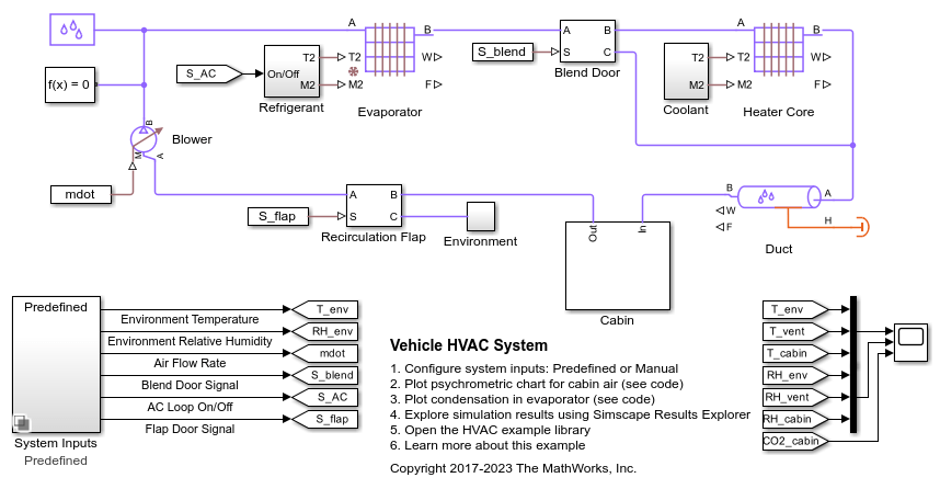
Aircraft Environmental Control System
Models an aircraft environmental control system (ECS) that regulates pressure, temperature, humidity, and ozone (O3) to maintain a comfortable and safe cabin environment. Cooling and dehumidification are provided by the air cycle machine (ACM), which operates as an inverse Brayton cycle to remove heat from pressurized hot engine bleed air. Some hot bleed air is mixed directly with the output of the ACM to adjust the temperature. Pressurization is maintained by the outflow valve in the cabin. This model simulates the ECS operating from a hot ground condition to a cold cruise condition and back to a cold ground condition.

Medical Ventilator with Lung Model
Models a positive-pressure medical ventilator system. A preset flow rate is supplied to the patient. The lungs are modeled with the Translational Mechanical Converter (MA), which converts moist air pressure into translational motion. By setting the Interface cross-sectional area to unity, displacement in the mechanical translational network becomes a proxy for volume, force becomes a proxy for pressure, spring constant becomes a proxy for respiratory elastance, and damping coefficient becomes a proxy for respiratory resistance.
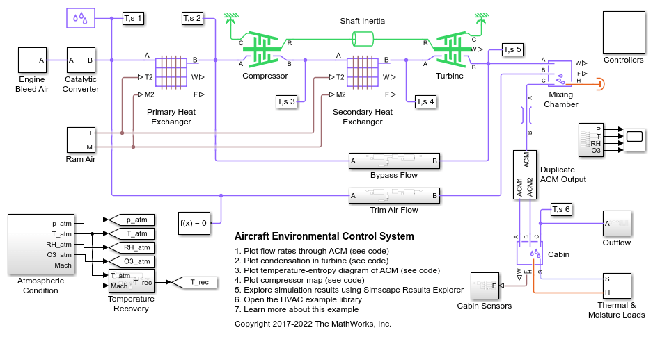
Pneumatic Actuator with Humidity
How the Simscape™ Foundation Library moist air components can be used to model a pneumatic actuator operating in a humid environment. The Directional Valve is a subsystem composed of four Variable Local Restriction (MA) blocks, and the Double-Acting Actuator is a subsystem composed of two Translational Mechanical Converter (MA) blocks in opposite mechanical orientation.