Protect Battery During Charge and Discharge for Electric Vehicle
This example shows how to efficiently charge and discharge a battery for an electric vehicle (EV) and handle battery faults. Portable electronics and EV widely use li-ion batteries as power source due to their high-energy density. But li-ion batteries also have safety issues due to extreme conditions such as over-discharge, over-charge, high temperature, and low temperature. These extreme conditions can damage the battery and effect its performance in the long term. In some cases they can cause loss of stability which leads to thermal runaway.
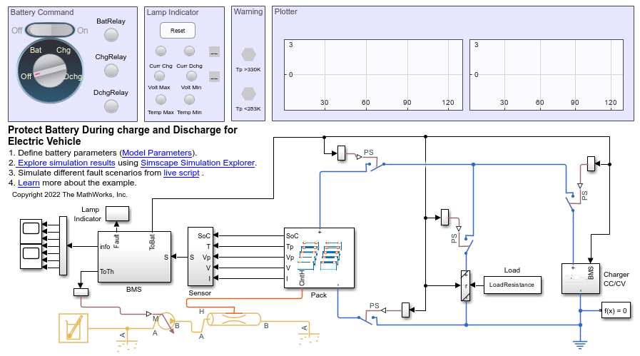
In this example, two circuit breakers connect the positive terminal and the negative terminal of the battery to the load circuit. Two more circuit breakers connect or disconnect the charging or discharging circuits. A basic control strategy operates these circuit breakers to put the battery in charge or discharge mode and to disconnect the battery during fault conditions.
Model Overview
Open the model batt_BatteryManagementSystem.slx.
clearvars
disp('Start battery plant model simulations workflow');
Start battery plant model simulations workflow
% Open the model
open_system('batt_BatteryManagementSystem.slx');
Load parameter files.
batt_BatteryManagementSystem_param; % Load model parameters
batt_packBTMSExampleLib_param; % Load battery pack parameters
Load data for LoadResistance and LoadCurrent for the drive run.
load('batt_BatteryManagementSystem_Drive.mat');Battery Module
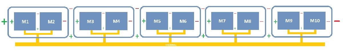
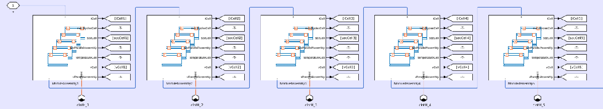
The battery comprises a battery pack of 400V, generally used in electric vehicles. Since a single cell cannot provide such voltage or power levels, multiple cells are connected in series and parallel to create the desired battery pack. The battery pack in this example comprises 10 modules, each with 11 series-connected parallel sets (p-sets). Each p-set comprises three cells in series. All modules are connected in series to form a pack of 330 cells.
To create the module used in the battery pack of this example, see the Build Model of Battery Module with Thermal Effects example.
Open the pack subsystem.
 % Show battery Pack
open_system('batt_BatteryManagementSystem/Pack','force')
Mode Control Dashboard
In an electric vehicle, you can control the charging and discharging operations of the battery.
To start the car, the key is turned which connects the battery circuit breakers and connects the battery to the system of the car.
While driving, the battery is in discharge mode.
When you connect the car to a charger, the battery is in charging mode.
In a car, the discharging and charging modes are mutually exclusive. This example emulates this scenario by implementing a charging control dashboard in the model, called Battery Command. This dashboard comprises a rotary switch for manual operations, an on-off switch for automatic operations, and indication lamps.
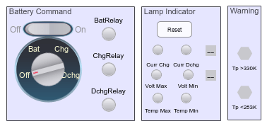
Use the rotary switch to choose between the charging and discharging modes manually. The position of the rotary switch affects the battery mode:
Off — The battery is disconnected.
Bat — The battery is connected.
Chg — The battery is charging.
Dchg — The battery is discharging.
Use the on-off switch to switch between modes automatically by setting the switch to On and by specifying the BatCmd variable. When the BatCmd variable is equal to:
0 — The battery is disconnected.
1 — The battery is connected.
2 — The battery is charging.
3 — The battery is discharging.
The indication lamps show which mode the battery is currently operating in. When the lamps are red, the specific mode is off. When the lamps are green, the specific mode is on. The model also contains indication lamps that track fault appearances and a Reset button to reset all the faults to zero for testing purposes. A red lamp indicates the presence of a fault.
Battery Management System
The battery management system (BMS) manages all the battery operations and keeps it within operational limits. The BMS maintains the current, voltage, and temperature of the pack within safe limits during the charging and discharging operations. In this example, the BMS controls the circuit breakers to protect the battery pack based on the pack sensor data and on estimated parameters such as the state-of charge (SOC) and the discharge and charge current limits. For temperature control, the BMS controls the flow of coolant by using an "On-Off" flow control block.
To open the BMS subsystem, at the MATLAB® Command Window, enter:
 % Show battery BMS
open_system('batt_BatteryManagementSystem/BMS','force')
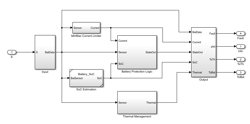
The BMS in this example comprises four different components: SoC estimation, MinMax Current Limiter, Thermal Management, and Battery Protection Logic.
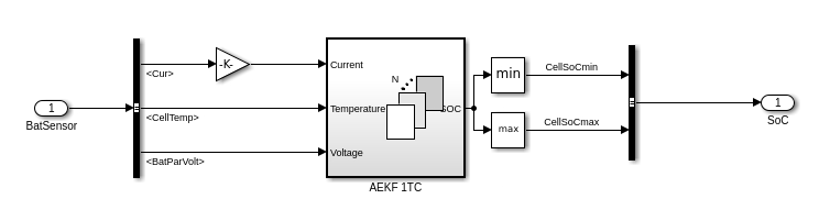
SoC Estimation
A battery SOC provides the remaining charge left inside the battery. This value is an estimation based on many different parameters. There are different ways to estimate the SOC of a battery. This example uses an extended Kalman filter estimation strategy.
To open the SoC Estimation subsystem, at the MATLAB Command Window, enter:
% Show SoC estimator
open_system('batt_BatteryManagementSystem/BMS/SoC Estimation','force')
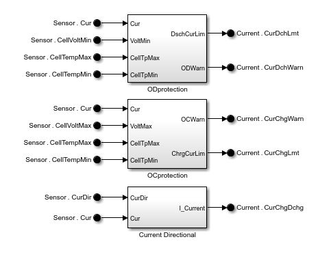
Current Limiter
The current state of the battery, such as the battery voltage and temperature, defines the over-discharge and over-charge current limits of the battery for protection of the pack. For example, while discharging, if the temperature is high, you must reduce the current that the electric vehicle withdraws from the battery. If the voltage of the battery is low and the vehicle withdraws too much current from the battery, it can cause damage to the cells and must be limited.
To open the Current Limiter subsystem, at the MATLAB Command Window, enter:
% Show Current limit calculation
open_system('batt_BatteryManagementSystem/BMS/MinMax Current Limiter','force')
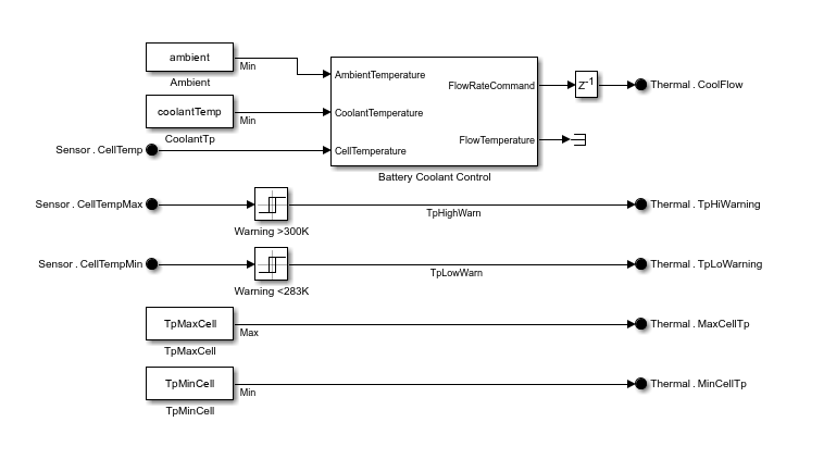
Thermal Control
For a safe operation of the battery, the battery temperature must be within specified limits. To control the temperature, you must remove the excess heat by using a coolant circuit. The flow of the coolant controls how much heat you can remove from the battery pack. In this example, an on-off control block manages the coolant circuit.
If the temperature is greater than a threshold value, the pump switches on. When the temperature is lower than the lowest threshold value, the pump switches off.
To open the Thermal Management subsystem, at the MATLAB Command Window, enter:
% Show Thermal management control
open_system('batt_BatteryManagementSystem/BMS/Thermal Management','force')
Battery Protection Logic
The battery protection logic is a state-flow logic that takes the battery parameters, sensor data, and user input from the charging control dashboard to generate the signal for the relay operation, state of the battery, and fault analysis of the battery.
To open the Battery Protection Logic subsystem, at the MATLAB Command Window, enter:
% Show protection stateflow
open_system('batt_BatteryManagementSystem/BMS/Battery Protection Logic/State Flow' ...
    ,'force')
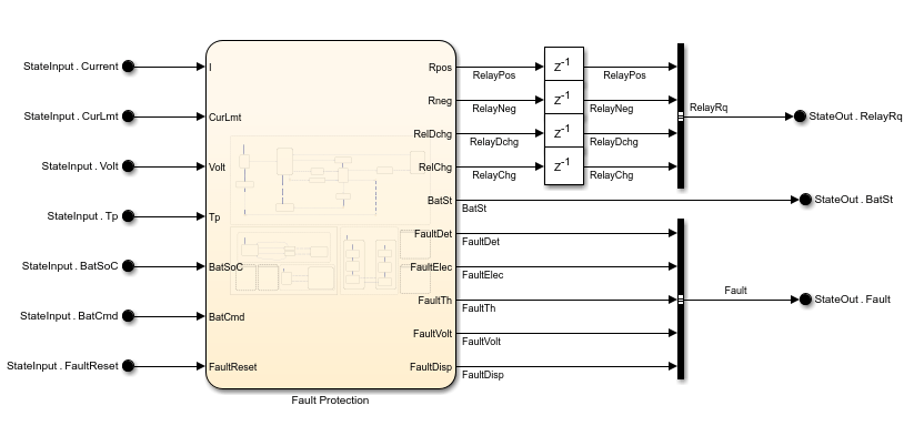
For fault protection, a counter records the triggering of current and voltage faults. When there are more than five faults, the battery protection logic disconnects the battery from the load until you reset the count. The counter does not record thermal faults. The battery is disconnected at the first thermal fault appearance. While discharging, if the battery SOC is lower than a specific limit, the protection logic disconnects the battery. While charging, if the battery SoC is greater than the upper threshold, the protection logic disconnects the battery from the charging circuit.
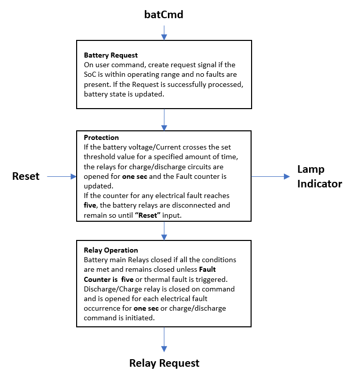
This flow chart shows the logic inside Fault Protection stateflow block. The logic follows these steps:
Battery Request — Put the battery in ideal, charge, or discharge mode according to the received input.
Protection — Check if the battery parameter (Current, Voltage and Temperature) crosses the threshold and generate faults.
Relay Operation — Operate the battery, charge, and discharge relays based on the request and fault status.
Fault Simulations
Battery faults occur when the battery is put in extreme scenarios.
Open the model batt_BatteryManagementSystem.slx.
open_system('batt_BatteryManagementSystem/','force')
Fault During Battery Charging
In charge mode, a battery can experience these faults:
Overvoltage fault — An incompatible device charges the battery beyond its rated voltage.
Overcurrent fault — A current higher than the allowed limit charges the battery.
While charging, as the voltage and temperature of the battery increase, the charging current limit decreases. If the current limit goes below the charging current, a charging fault triggers and the charging circuit is disconnected from the battery for protection. After five fault occurrences, the battery circuit breakers disconnect for the rest of the simulation.
batt_BatteryManagementSystem_param; % Load Simulation parameters
ChargerCC_A = 125; % charger max charging current (Ah)
initialPackSOC = 0.5; % Initial SoC of the pack set to low
BatCmdData=timeseries([0;0;1;1;2;2],[0;1.99;2;2.99;3;130],'Name','BatCmdData'); % Battery input for vehicle in charge at three sec
batt_packBTMSExampleLib_param; % Load battery parameters with the new data
sim('batt_BatteryManagementSystem.slx'); % Simulate the model
%% Plot for comparison
% Plot for current
figure
plot(logsout_batt_BatteryManagementSystem.get("CurDisp").Values,'r-');
hold on
plot(logsout_batt_BatteryManagementSystem.get("<CurChgLmt>").Values  ,'b-');
plot(logsout_batt_BatteryManagementSystem.get("<CurDchgLmt>").Values  ,'g-');
hold off;legend("Battery pack current","Chg Cur Lmt","Dchg Cur Lmt");
xlabel("Time (s)");ylabel("Current [A]");title("Battery Pack Current");
![Figure contains an axes object. The axes object with title Battery Pack Current, xlabel Time (s), ylabel Current [A] contains 3 objects of type line. These objects represent Battery pack current, Chg Cur Lmt, Dchg Cur Lmt.](../../examples/simscapebattery/win64/ProtectBatteryChargeAndDischargeForElectricVehicleExample_11.png)
%% Plot Voltage
figure
simlog_handles(2) = subplot(3, 1, 2);
plot(logsout_batt_BatteryManagementSystem.get("<BatVolt>").Values,'b-');
legend("Battery pack voltage");
xlabel("Time (s)");ylabel("Volt [V]");title("Battery Voltage");
![Figure contains an axes object. The axes object with title Battery Voltage, xlabel Time (s), ylabel Volt [V] contains an object of type line. This object represents Battery pack voltage.](../../examples/simscapebattery/win64/ProtectBatteryChargeAndDischargeForElectricVehicleExample_12.png)
For higher values of SOC, the cell voltage is closer to the full charge voltage. A high charging current can overcharge the battery or increase the battery voltage too much, which triggers an overvoltage fault. After five fault occurrences, the battery circuit breakers disconnects for rest of the simulation.
batt_BatteryManagementSystem_param; % Load Simulation parameters
MaxVoltLmt = 4.2; % cell max voltage limit
ChargerCC_A = 70; % charger max charging current
initialPackSOC = 0.95; % Initial SoC of the pack set to high
BatCmdData=timeseries([0;0;1;1;2;2],[0;1.99;2;2.99;3;130],'Name','BatCmdData'); % Battery input for vehicle in charge at three sec
batt_packBTMSExampleLib_param; % Load battery parameters with the new data
sim('batt_BatteryManagementSystem.slx'); % Simulate model
%% Plot for comparison
% Plot for current
figure
plot(logsout_batt_BatteryManagementSystem.get("CurDisp").Values,'r-');
hold on
plot(logsout_batt_BatteryManagementSystem.get("<CurChgLmt>").Values  ,'b-');
plot(logsout_batt_BatteryManagementSystem.get("<CurDchgLmt>").Values  ,'g-');
hold off;legend("Battery pack current","Chg Cur Lmt","Dchg Cur Lmt");
xlabel("Time (s)");ylabel("Current [A]");title("Battery Pack Current");
![Figure contains an axes object. The axes object with title Battery Pack Current, xlabel Time (s), ylabel Current [A] contains 3 objects of type line. These objects represent Battery pack current, Chg Cur Lmt, Dchg Cur Lmt.](../../examples/simscapebattery/win64/ProtectBatteryChargeAndDischargeForElectricVehicleExample_13.png)
%% Plot Voltage
figure
simlog_handles(2) = subplot(3, 1, 2);
plot(logsout_batt_BatteryManagementSystem.get("<BatVolt>").Values,'b-');
legend("Battery pack voltage");
xlabel("Time (s)");ylabel("Volt [V]");title("Battery Voltage");
![Figure contains an axes object. The axes object with title Battery Voltage, xlabel Time (s), ylabel Volt [V] contains an object of type line. This object represents Battery pack voltage.](../../examples/simscapebattery/win64/ProtectBatteryChargeAndDischargeForElectricVehicleExample_14.png)
Fault During Battery Discharging
In discharge mode, a battery can experience these faults:
Undervoltage fault — The battery discharges beyond its minimum rated voltage.
Overcurrent fault — A current higher than the allowed limit discharges the battery.
While discharging, as the battery voltage decreases and the battery temperature increases, the discharging current limit decreases. If the current limit goes below the discharging current, a discharging fault triggers. If the cell voltage goes below the minimum voltage limit, a voltage fault triggers. For any of these faults the discharging circuit is disconnected from the battery for protection. After five fault occurrences, the battery circuit breakers disconnect for the rest of the simulation.
batt_BatteryManagementSystem_param; % Load Simulation parameters
load('batt_BatteryManagementSystem_Drive.mat') % load drive data
MinVoltLmt=3.2; % battery minimum voltage limit
initialPackSOC = 0.25; % Initial SoC of the pack set to low
BatCmdData=timeseries([0;0;1;1;3;3],[0;1.99;2;2.99;3;130],'Name','BatCmdData'); % Battery input for vehicle in discharge at three sec
batt_packBTMSExampleLib_param; % Load battery parameters with the new data
sim('batt_BatteryManagementSystem.slx'); % Simulate model
%% Plot for comparison
% Plot for current
figure
plot(logsout_batt_BatteryManagementSystem.get("CurDisp").Values,'r-');
hold on
plot(logsout_batt_BatteryManagementSystem.get("<CurChgLmt>").Values  ,'b-');
plot(logsout_batt_BatteryManagementSystem.get("<CurDchgLmt>").Values  ,'g-');
hold off;legend("Battery pack current","Chg Cur Lmt","Dchg Cur Lmt");
xlabel("Time (s)");ylabel("Current [A]");title("Battery Pack Current");
![Figure contains an axes object. The axes object with title Battery Pack Current, xlabel Time (s), ylabel Current [A] contains 3 objects of type line. These objects represent Battery pack current, Chg Cur Lmt, Dchg Cur Lmt.](../../examples/simscapebattery/win64/ProtectBatteryChargeAndDischargeForElectricVehicleExample_15.png)
%% Plot Voltage
figure
simlog_handles(2) = subplot(3, 1, 2);
plot(logsout_batt_BatteryManagementSystem.get("<BatVolt>").Values,'b-');
legend("Battery pack voltage");
xlabel("Time (s)");ylabel("Volt [V]");title("Battery Voltage");
![Figure contains an axes object. The axes object with title Battery Voltage, xlabel Time (s), ylabel Volt [V] contains an object of type line. This object represents Battery pack voltage.](../../examples/simscapebattery/win64/ProtectBatteryChargeAndDischargeForElectricVehicleExample_16.png)
Battery Thermal Fault
Thermal faults trigger if the battery temperature goes beyond the safe operating range. A simple on-off strategy controls the flow of coolant in the thermal circuit to manage the battery temperature.
To simulate a thermal fault, this example first turns off the coolant control so that the temperature in the battery is unregulated. The initial temperature of the battery is high. A high current charges the battery and brings its temperature to values beyond the safe operating range. This triggers the thermal fault and the battery circuit breakers disconnect for the rest of the simulation.
batt_BatteryManagementSystem_param; % Load Simulation parameters
% Temperature parameter to "switch on" flow for thermal control
CoolantSwitchOnTp = MaxThLmt+5; % switch on temp set to 338.15 K (65 deg C)
% "Switch on" temperature for coolant flow set five degrees more than the max allowed temperature for battery
initialBattTemp=328.15; % Initial temperature set to high(K) - 55 deg Celsius
ChargerCC_A = 75; % charger max charging current
initialPackSOC = 0.5; % Initial SoC of the pack set to low
BatCmdData=timeseries([0;0;1;1;2;2],[0;1.99;2;2.99;3;130],'Name','BatCmdData'); % Battery input for vehicle in charge at three sec
batt_packBTMSExampleLib_param; % Load battery parameters with the new data
sim('batt_BatteryManagementSystem.slx'); % Simulate the model
%% Plot for comparison
% Plot for current
figure
plot(logsout_batt_BatteryManagementSystem.get("CurDisp").Values,'r-');
hold on
plot(logsout_batt_BatteryManagementSystem.get("<CurChgLmt>").Values  ,'b-');
plot(logsout_batt_BatteryManagementSystem.get("<CurDchgLmt>").Values  ,'g-');
hold off;legend("Battery pack current","Chg Cur Lmt","Dchg Cur Lmt");
xlabel("Time (s)");ylabel("Current [A]");title("Battery Pack Current");
![Figure contains an axes object. The axes object with title Battery Pack Current, xlabel Time (s), ylabel Current [A] contains 3 objects of type line. These objects represent Battery pack current, Chg Cur Lmt, Dchg Cur Lmt.](../../examples/simscapebattery/win64/ProtectBatteryChargeAndDischargeForElectricVehicleExample_17.png)
%% Plot Voltage
figure
simlog_handles(2) = subplot(3, 1, 2);
plot(logsout_batt_BatteryManagementSystem.get("<BatVolt>").Values,'b-');
legend("Battery pack voltage");
xlabel("Time (s)");ylabel("Volt [V]");title("Battery Voltage");
![Figure contains an axes object. The axes object with title Battery Voltage, xlabel Time (s), ylabel Volt [V] contains an object of type line. This object represents Battery pack voltage.](../../examples/simscapebattery/win64/ProtectBatteryChargeAndDischargeForElectricVehicleExample_18.png)
%% Plot for Temp
figure
plot(logsout_batt_BatteryManagementSystem.get("<TpMax>").Values,'r-')
legend("Battery pack Temp");xlabel("Time (s)");ylabel("Temp [K]");
title("Battery Temperature")
![Figure contains an axes object. The axes object with title Battery Temperature, xlabel Time (s), ylabel Temp [K] contains an object of type line. This object represents Battery pack Temp.](../../examples/simscapebattery/win64/ProtectBatteryChargeAndDischargeForElectricVehicleExample_19.png)
Results from Real-Time Simulation
This example has been tested on these platforms:
Speedgoat™ Performance real-time target machine with an Intel® 3.5 GHz i7 multi-core CPU and 4 GB RAM.
dSPACE® SCALEXIO LabBox with Intel® Core XEON E3-1275v3 at 3.5GHz and 4 GB RAM.
You can run this model in real time with a step size of 400 microseconds by using the Simscape local solver. For small sample rates, a task overrun might occur during the initial task execution due to a cold cache. To avoid this overrun, if the selected platform supports these options, relax the start-up behavior by specifying a limited number of task overruns or increasing the sample time of periodic tasks during the start-up phase of the real-time application.