Build Model of Battery Pack with Multi-Module Cooling Plate
This example shows how to create and build a Simscape™ system model of a pack with a multi-module cooling plate by using Simscape Battery™ software. Large cooling plates that span across several battery modules are common in the design of battery systems in the automotive and consumer electronics sector. In this example, you thermally couple several modules to a single battery cooling plate. To create the system model of a battery Pack, you must first create the Cell, ParallelAssembly, Module, and ModuleAssembly objects that comprise the battery pack, and then use the buildBattery function. This function creates a library in your working folder that contains a system model block of a battery pack. Use this model as reference in your simulations. You can modify the run-time parameters for this model block, such as the battery cell resistance or the battery open-circuit voltage, after you create the model. To define the run-time parameters, specify them in the block mask of the generated Simscape models or use the MaskParameters argument of the buildBattery function.
Create Battery Pack Object
To create a battery pack object, you must first design and create the foundational elements of the battery pack.
A battery pack comprises multiple battery module assemblies. These module assemblies, in turn, comprise a number of battery modules connected electrically in parallel or series. You can set the specific topological configuration or geometrical arrangement of the cells inside each module at the parallel assembly level. This figure shows the hierarchy of a battery pack object in a bottom-up view:

Create Cell Object
To create the Pack object, first create a Cell object with a cylindrical format. The CylindricalGeometry object defines the cylindrical geometrical arrangement of the battery cell. To create a CylindricalGeometry object, use the batteryCylindricalGeometry function. You can specify the height as the first argument and the radius as the second argument.
cylindricalGeometry = batteryCylindricalGeometry;
Now use this CylindricalGeometry object to create a cylindrical battery cell.
cylindricalCell = batteryCell(cylindricalGeometry)
cylindricalCell =
  Cell with properties:

            Geometry: [1×1 simscape.battery.builder.CylindricalGeometry]
    CellModelOptions: [1×1 simscape.battery.builder.CellModelBlock]
                Mass: 0.1000 (kg)
            Capacity: 5 (A*hr)
              Energy: 50 (W*hr)

Show all properties
By default, a Cell object uses the Battery Equivalent Circuit block as Simscape cell model block.
disp(cylindricalCell.CellModelOptions.CellModelBlockPath);
batt_lib/Cells/Battery Equivalent Circuit
Use the Cell object to simulate the thermal effects of the battery cell by using a simple 1-D model. To simulate the thermal effects of the battery cell, in the BlockParameters property of the CellModelOptions object of the Cell object, set the ThermalModel property to "LumpedThermalMass". You can define the thermal boundary conditions for battery parallel assemblies and modules only if you first define a thermal model at the cell level.
cylindricalCell.CellModelOptions.BlockParameters.ThermalModel = "LumpedThermalMass";Create ParallelAssembly Object
A parallel assembly comprises multiple battery cells connected electrically in parallel under a specific topological configuration or geometrical arrangement. In this example, you create a parallel assembly of three cylindrical cells.
To create the ParallelAssembly object, use the batteryParallelAssembly function. Define the Cell object as the first argument and the number of cells connected in parallel as the second argument. To specify the additional properties, use the name-value arguments Rows and Topology.
parallelAssembly = batteryParallelAssembly(cylindricalCell,3, ...
    Rows=3, ...
    Topology="Square");
Create Module Object
A battery module comprises multiple parallel assemblies connected electrically in series. In this example, you create two battery modules that are each comprised of four parallel assemblies. The first module uses grouped and lumped model resolution settings. The second module uses a detailed module resolution. The latter module provides more battery states that are useful for battery control.
To create these Module objects, use the batteryModule function. Define the ParallelAssembly object as the first argument and the number of parallel assemblies in series as the second argument. To specify the additional properties, use the name-value arguments SeriesGrouping and ParallelGrouping.
lumpedModule= batteryModule(parallelAssembly,4);

groupedModule1 = batteryModule(parallelAssembly,4, ...
    SeriesGrouping=[1 3], ...
    ParallelGrouping=[3 1]);

groupedModule2 = batteryModule(parallelAssembly,4, ...
    SeriesGrouping=[3 1], ...
    ParallelGrouping=[1 3]);
Create ModuleAssembly Object
A battery module assembly comprises multiple battery modules connected in series or in parallel. In this example, you create a battery module assembly of eight different modules, with a gap of 0.01 m between each module. By default, the ModuleAssembly object electrically connects the modules in series.
To create the ModuleAssembly object, use the batteryModuleAssembly function and define the Module objects as the first argument. To specify the gap between each module, use the name-value argument InterModuleGap.
moduleAssembly = batteryModuleAssembly([groupedModule1,repmat(lumpedModule,1,6),groupedModule2], ...
    InterModuleGap=simscape.Value(0.01,"m"));
Create Pack Object
You now have all the foundational elements to create your battery pack. A battery pack comprises multiple module assemblies connected in series or in parallel. In this example, you create a battery pack of five identical module assemblies with a gap of 0.01 m between each module assembly and a coolant thermal path.
To create the Pack object, use the batteryPack function and specify the ModuleAssembly object as the first argument. To specify the additional properties, use the name-value arguments CoolantThermalPath and InterModuleAssemblyGap.
pack = batteryPack(repmat(moduleAssembly,1,5), ...
    CoolantThermalPath="CellBasedThermalResistance", ...
    InterModuleAssemblyGap=simscape.Value(0.01,"m"));
Add Cooling Plate to Pack
To add a single cooling plate across all battery modules, you must first define a cooling plate boundary. Set the CoolingPlate property of the batterypack object to "Bottom".
pack.CoolingPlate = "Bottom";To specify the cooling plate block from the Simscape Battery library, use the CoolingPlateBlockPath property. In this example, you use the Parallel Channels block to model the cooling plate.
pack.CoolingPlateBlockPath = "batt_lib/Thermal/Parallel Channels";To obtain a higher resolution in the temperature and the state of charge (SOC) signals for battery control, you can use different model resolutions for each module inside the pack. To parameterize the cooling plate, you can visualize the thermal node information at the pack level. This thermal node information propagates to the generated model after you use the buildBattery function.
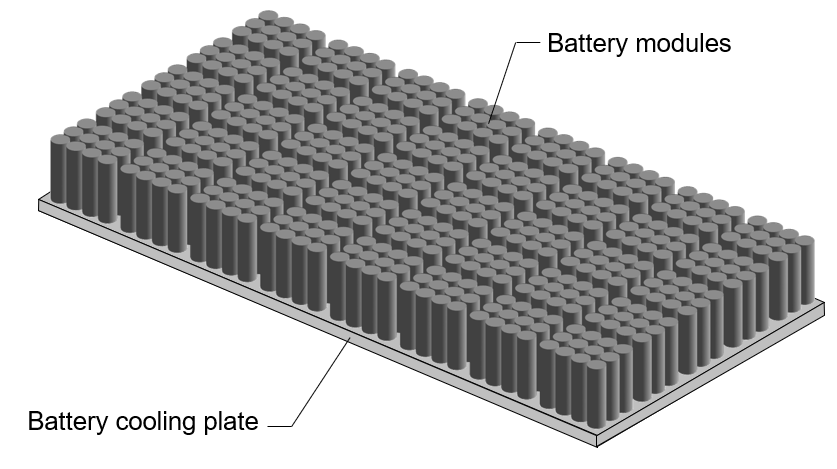
Alternatively, to individually define cooling plates for each module assembly, modify the CoolingPlate and CoolingPlateBlockPath properties of each module assembly inside the batterypack object. This figure shows a system with a cooling plate at the bottom surface of a battery.
View Information About Thermal Node Connectivity
To visualize the thermal connectivity information of the batterypack object, use the ThermalNodes property.
thermalNodes = pack.ThermalNodes.Bottom;
disp(thermalNodes)
     Locations: [70×2 double]
    Dimensions: [70×2 double]
      NumNodes: 70
This property contains information about the thermal interface between the battery and the cooling plate, including the number of nodes, the location of the interface areas in Cartesian coordinates, and the dimensions of each interface area.
disp(thermalNodes.NumNodes)
70
Visualize Battery Pack and Check Model Resolution
To obtain the number of Battery Equivalent Circuit blocks used for the simulation, use the NumModels property of your batterypack object.
disp(pack.NumModels)
70
To visualize the battery pack before you build the system model and to view its model resolution, create the figure where you want to visualize your pack and then use the batteryChart function. To view the model resolution of the pack, specify the SimulationStrategyVisible name-value argument as "On".
f = uifigure(Color="w");
tl = tiledlayout(1,2,Parent=f,TileSpacing="Compact");
nexttile(tl)
packChart1 = batteryChart(tl,pack);
nexttile(tl)
packChart2 = batteryChart(tl,pack,SimulationStrategyVisible="On");

Build Simscape Model of Pack Object
After you create your battery objects, you need to convert them into Simscape models to use them in block diagrams. You can then use these models as references for system integration and requirement evaluation, cooling system design, control strategy development, hardware-in-the-loop, and many more applications.
To create a library that contains the Simscape Battery model of the Pack object, use the buildBattery function. To create a script where you can individually define the coolant thermal resistance parameters for each thermal connection, as well as all other parameters within your battery, set the MaskParameters argument of the buildBattery function to "VariableNamesByType".
Create the packWithMultiModuleCoolingPlate_lib and packWithMultiModuleCoolingPlate SLX library files in your working folder. The packWithMultiModuleCoolingPlate_lib library contains the Modules and ParallelAssemblies sublibraries.
buildBattery(pack,LibraryName="packWithMultiModuleCoolingPlate", ...
    MaskParameters="VariableNamesByType", ...
    MaskInitialTargets="VariableNamesByInstance", ...
    Verbose="off");
To access the Simscape models of your Module and ParallelAssembly objects, open the packWithMultiModuleCoolingPlate_lib SLX file, double-click the sublibrary, and drag the Simscape blocks in your model.
The packWithMultiModuleCoolingPlate library contains the Simscape models of your Pack and ModuleAssembly objects. The build process automatically generates the Simscape model of the battery pack. This model includes the domain connections between module assemblies and cooling plates. The software also adds a cooling plate connector to concatenate arrays of thermal nodes from all module assembly blocks, for compatibility with the cooling plate block.

See Also
Battery Builder | Pack | Parallel
Channels