Microstrip Ultra-Wideband Bandpass Filter with Cascaded Broadband Bandpass and Bandstop Filters
This example shows how to create a compact ultra-wideband filter by connecting a broadband bandstop filter with a broadband bandpass filter.
In the recent years, wireless communication systems have increasing demands for broader bandwidth and research focuses on ultra-wideband filters. The frequency spectrum adopted for the ultra-wideband system in [1] is 3.1–10.6 GHz.
The proposed structure has a Rogers RO4003 substrate with dielectric constant of 3.38, loss tangent of 0.0027, and substrate thickness of 0.508 mm, respectively. The proposed filter exhibits a passband within 3.42–12 GHz and a return loss is greater than 15 dB. The filter also has a greater-than-15-dB insertion loss and the stopband is within 12.85–28.5 GHz.
Design of Broadband Bandpass filter
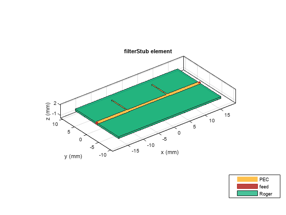
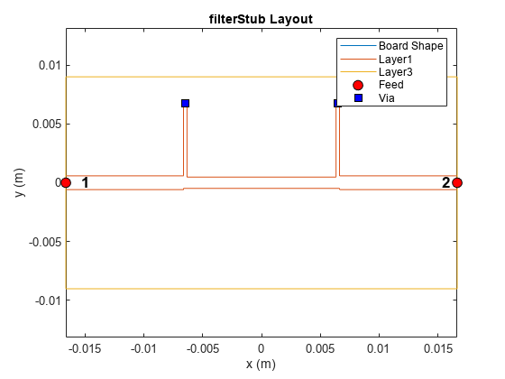
The ultra-wideband bandpass filter composes of a one-half wavelength transmission line shunted with two quarter-wavelength short stubs at the input and output port.
Create the bandpass filter using a filterStub object with the designed dimensions in [1] and visualize it.
filterBpass = filterStub;
sub = dielectric('Name',{'Roger'},'EpsilonR',3.38,'LossTangent',0.0027,'Thickness',0.508e-3,'FrequencyModel','Constant');
filterBpass.Substrate = sub;
filterBpass.Height = 0.508e-3;
filterBpass.StubLength = [6.75e-3,6.75e-3];
filterBpass.StubWidth = [0.3e-3,0.3e-3];
filterBpass.StubDirection = [1 1];
filterBpass.StubOffsetX = [-6.48e-3 6.48e-3];
filterBpass.StubShort = [1 1];
filterBpass.SeriesLineLength = 13.26e-3;
filterBpass.SeriesLineWidth = 0.96e-3;
filterBpass.PortLineLength = 10e-3;
filterBpass.PortLineWidth = 1.17e-3;
filterBpass.GroundPlaneWidth =  0.018;
figure; show(filterBpass);
Analyze the s-parameters behavior of the filter at the UWB frequency range using manual meshing with MaxEdgeLength of 0.01.
figure; mesh(filterBpass,'MaxEdgeLength',0.01)
sparBpass = sparameters(filterBpass,linspace(0.1e9,15e9,31));
figure; rfplot(sparBpass)
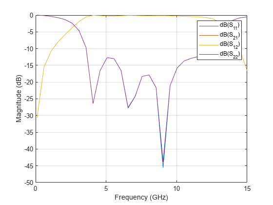
Observe that the bandpass filter exhibits a passband behavior in the frequency range of 3.5 GHz to 12 GHz, with return loss greater than -10dB.
Design of Broadband Bandstop Filter
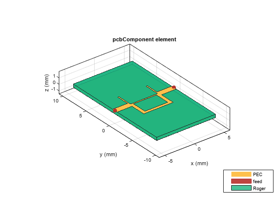
The structure of a broadband bandstop filter consists of one transmission line with a half-wavelength electric length in parallel with another transmission line with one-wavelength electric length.
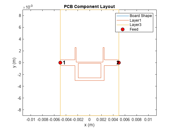
Create the bandstop filter using pcbComponent object with the designed dimensions in [1], and visualize it.
seriesLtop = 4.57e-3;
seriesWtop = 0.2e-3;
seriesWbtm = 0.45e-3;
shuntWtop = 0.2e-3;
shuntLtop = 2.48e-3;
shuntLbtm = 2.93e-3;
shuntWbtm = 0.55e-3;
PL = 2.5e-3;
PW = 0.97e-3;
gndL = (2*PL)+(2*shuntWtop)+seriesLtop;
gndW = 0.018;
h = 0.508e-3;
filterBstop = pcbComponent;
filterBstop.BoardThickness = h;
gnd = traceRectangular('Length',gndL,'Width',gndW);
filterBstop.BoardShape = gnd;
InPort =  traceRectangular('Length',PL,'Width',PW,'Center',[-gndL/2+PL/2,0]);
OutPort =  traceRectangular('Length',PL,'Width',PW,'Center',[gndL/2-PL/2,0]);
ShutLineTopIn =  traceRectangular('Length',shuntWtop,'Width',shuntLtop+seriesWtop/2,...
              'Center',[-gndL/2+PL+shuntWtop/2,shuntLtop/2+seriesWtop/2-seriesWtop/4]);
ShutLineTopOut =  traceRectangular('Length',shuntWtop,'Width',shuntLtop+seriesWtop/2,...
              'Center',[-(-gndL/2+PL+shuntWtop/2),shuntLtop/2+seriesWtop/2-seriesWtop/4]);
seriesLbtm = seriesLtop-(2*(shuntWbtm-shuntWtop));

SeriesLineTop =  traceRectangular('Length',seriesLtop+2*seriesWtop+PL/4,'Width',seriesWtop,...
              'Center',[0,0]);
ShutLineBtmIn =  traceRectangular('Length',shuntWbtm,'Width',shuntLbtm+seriesWtop/2,...
              'Center',[-gndL/2+PL+shuntWbtm/2,-shuntLbtm/2-seriesWtop/2+seriesWtop/4]);
ShutLineBtmOut =  traceRectangular('Length',shuntWbtm,'Width',shuntLbtm+seriesWtop/2,...
              'Center',[-(-gndL/2+PL+shuntWbtm/2),-shuntLbtm/2-seriesWtop/2+seriesWtop/4]);

SeriesLineBtm =  traceRectangular('Length',seriesLtop+seriesWbtm/2,'Width',seriesWbtm,...
              'Center',[0,-seriesWtop/2-shuntLbtm+seriesWbtm/2]);


Bstop = InPort+OutPort+ShutLineTopIn+ShutLineTopOut+ShutLineBtmIn+...
              ShutLineBtmOut+SeriesLineTop+SeriesLineBtm;

filterBstop.Layers ={Bstop,sub,gnd};
filterBstop.FeedLocations = [-gndL/2,0,1,3;gndL/2,0,1,3];
filterBstop.FeedDiameter = PW/2;
figure; show(filterBstop);
Analyze the s-parameters behavior of the filter in the frequency range of 12 to 32 GHz.
sparBstop = sparameters(filterBstop,linspace(12e9,32e9,31));
figure; rfplot(sparBstop)
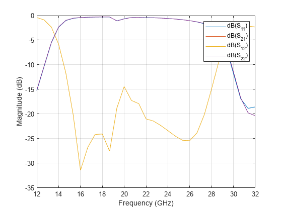
You can observe that the bandstop filter exhibits a bandstop behavior in the frequency range of 14 GHz to 28 Ghz with insertion loss greater than -10dB.
Design of Ultra-Wideband Filter
By cascading the bandpass filter and bandstop filter, you can create a new ultra-wideband filter to generate a wide passband and a broad stopband within the higher passband skirt simultaneously.
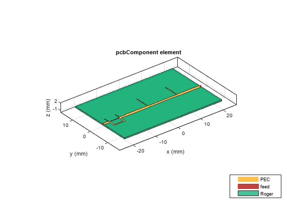
Cascade the broad bandpass and bandstop filter using pcbCascade object to create the ultra-wideband filter [1].
figure; layout(filterBstop);
figure; layout(filterBpass);
uwbFilter = pcbcascade(filterBstop,filterBpass,2,1);
gndL = uwbFilter.BoardShape.Length;
gndW = uwbFilter.BoardShape.Width + 10e-3;
gnd = traceRectangular('Length',gndL,'Width',gndW);
uwbFilter.BoardShape = gnd;
uwbFilter.Layers{3} = gnd;

viaYpt1 = uwbFilter.FeedLocations(1,2)+6.75e-3;
viaXpt1 = -(uwbFilter.BoardShape.Length)/2+(filterBstop.BoardShape.Length)+10e-3+0.3e-3/2;
viaXpt2 = -(uwbFilter.BoardShape.Length)/2+(filterBstop.BoardShape.Length)+10e-3+13.26e-3-0.3e-3+0.3e-3/2;
uwbFilter.ViaLocations = [viaXpt1,viaYpt1,1,3;viaXpt2,viaYpt1,1,3];
uwbFilter.ViaDiameter = 0.3e-3/2;
uwbFilter.FeedDiameter = [0.97e-3/2,1.17e-3/2];
figure; show(uwbFilter);
Analyze the filter performance in frequency range of 0.1GHz to 32 Ghz.
Use the mesh function to manually change the mesh and set the MaxEdgeLength property to 0.001 m
figure; mesh(uwbFilter,'MaxEdgeLength',0.001);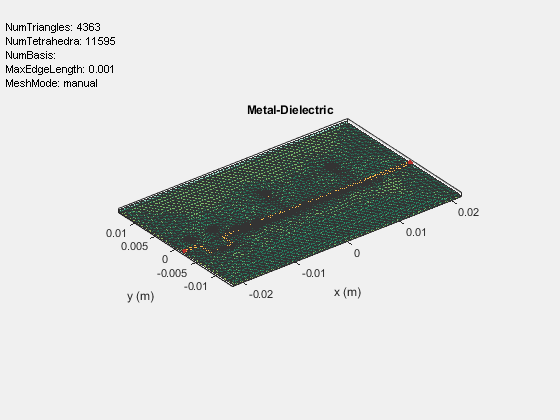
Use the memoryEstimate function to calculate the memory required to solve the structure.
memEst = memoryEstimate(uwbFilter,32e9)
memEst =
'6 GB'
As the memory requirement is around 3.4 Ghz, you will need more time to run the analysis in this live script. On the machine with 64 GB of RAM and Intel(R) Xeon(R) W-2133 CPU clocked @ 3.60 GHz processor, it takes around 2511.21 seconds time to calculate the s-parameters for 51 points. Therefore, this example includes a MAT file containing the sparameters data to analyze the filter characteristics.
The code used to compute the results is available in the Return Loss for UWB Filter section.
Load the MAT file and plot the s-parameters to analyze the return loss and insertion loss using the rfplot function.
 sparF =  load('sparam.mat');
 figure; rfplot(sparF.spar);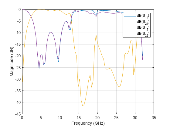
Return Loss for UWB Filter
% spar = sparameters(uwbFilter,linspace(0.1e9,32e9,51));
% figure; rfplot(spar);
Conclusion
You can develop a ultra-wideband bandpass filter by cascading a broadband bandpass filter and a broadband bandstop filter. By carefully selecting impedances of the transmission lines, bandwidths of both broadband bandpass and bandstop filter are independently design. This filter exhibits the passband behavior in the frequency range 3.5 GHz to 12 Ghz and stopband behavior in the frequency range of 12 Ghz to 28 Ghz. The filter [1] is appropriate for implementation in ultra-wideband systems due to its simple structure and attractive performance.
Reference
Ching-Wen Tang, Ming-Guang Chen, 'A Microstrip Ultra-Wideband Bandpass Filter With Cascaded Broadband Bandpass and Bandstop Filters', IEEE TRANSACTIONS ON MICROWAVE THEORY AND TECHNIQUES, VOL. 55, NO. 11, NOVEMBER 2007.