Finite Element Method Based Open Problem
This example shows how to create, visualize and analyze a Finite Element Method (FEM) based open problem.
Prerequisites
The example requires the Integro-Differential Modeling Framework for MATLAB add-on. To enable the add-on:
In the Home tab Environment section, click on Add-Ons. This opens the add-on explorer. You need an active internet connection to download the add-on.
Search for Integro-Differential Modeling Framework for MATLAB and click Install
To verify if the download is successful, run
matlab.addons.installedAddonsin your MATLAB® session command line.On Windows, to run the FEM based open problem, you must install the Windows Subsystem for Linux (WSL).
Create Variables
Create variable for the frequency range.
freq = linspace(1e9,5e9,21);
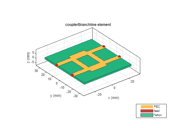
Create Branch-line Coupler
Create a branch-line coupler with default properties.
branchline = couplerBranchline;
Visualize the coupler.
figure
show(branchline)
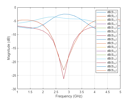
Use the sparameters function to calculate the S-parameters in the frequency range of 1 - 5 GHz. The default solver is a Method of Moments (MoM).
sparam_mom = sparameters(branchline,freq);
Plot the S-parameters of the coupler.
figure
rfplot(sparam_mom)
Create FEM based Branch-line Coupler
Convert the branch-line coupler to the pcbComponent object.
pcb = pcbComponent(branchline)
pcb =
  pcbComponent with properties:

              Name: 'couplerBranchline'
          Revision: 'v1.0'
        BoardShape: [1×1 antenna.Rectangle]
    BoardThickness: 0.0016
            Layers: {[1×1 antenna.Polygon]  [1×1 dielectric]  [1×1 antenna.Rectangle]}
        FeedFormat: 'FeedLocations'
     FeedLocations: [4×4 double]
      FeedDiameter: 0.0026
      ViaLocations: []
       ViaDiameter: []
      FeedViaModel: 'strip'
         Conductor: [1×1 metal]
              Tilt: 0
          TiltAxis: [0 0 1]
              Load: [1×1 lumpedElement]
        SolverType: 'MoM'
        IsShielded: 0
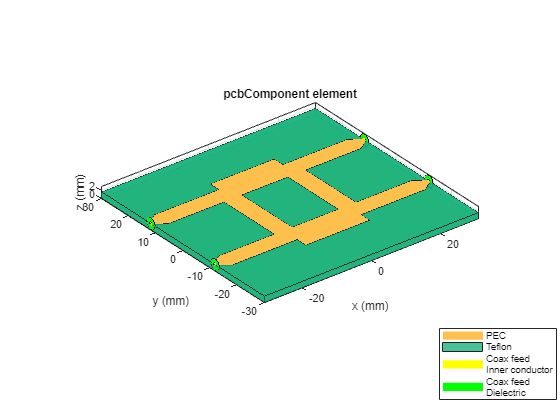
Set the SolverType property to 'FEM'.
pcb.SolverType = 'FEM';Visualize the FEM based coupler.
figure
show(pcb)
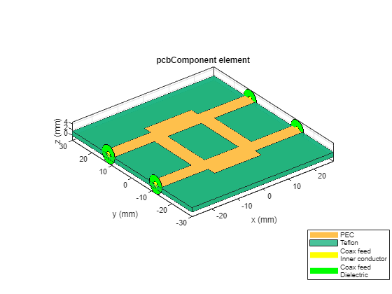
Design RF Connector
Unlike a delta gap source feed model in MoM, the FEM uses a coaxial wave port model. Use the design function to design a coaxial connector model.
c = design(RFConnector(PinLength=0),pcb);
Set the designed coaxial connector to the coupler.
pcb.Connector = c;
Visualize the coupler.
figure
show(pcb)
Calculate S-parameters
Use the sparameters function to calculate the S-parameters in the frequency range of 1 - 5 GHz.
The code is commented out. Remove the % when WSL is installed.
%sparam_fem = sparameters(pcb,freq);Plot the S-parameters of the coupler.
%figure
%rfplot(sparam_fem)