RF Budget Harmonic Balance Analysis of Low-IF Receiver, IP2 and NF
This example shows how to use the rfbudget object's harmonic balance solver to analyze a low-IF (intermediate frequency) receiver RF budget for second-order intercept point (IP2), the second-order intercept point and to compute a more accurate noise figure (NF) that correctly accounts for system nonlinearity and noise-folding.
Use amplifier and modulator objects to construct the 2-port RF elements in a low-IF receiver design, along with their output second-order intercept point (OIP2) specifications. You can turn off the default ideal image reject and channel select filtering in the modulator with the ImageReject and ChannelSelect logical name-value pairs.
Compute RF budget results by cascading the elements together into an RF system with rfbudget. The rfbudget object enables design exploration and visualization at the MATLAB command-line. It also enables automatic RF Blockset model and measurement testbench generation.
a1 = amplifier('Name','RFAmplifier', ...
    'Gain',11.53, ...
    'NF',1.53, ...
    'OIP2',35);

d = modulator('Name','Demodulator', ...
    'Gain',-6, ...
    'NF',4, ...
    'OIP2',50, ...
    'LO',2.03e9, ...
    'ConverterType','Down', ...
    'ImageReject',false, ...
    'ChannelSelect',false);

a2 = amplifier('Name','IFAmplifier', ...
    'Gain',30, ...
    'NF',8, ...
    'OIP2',37);

b = rfbudget('Elements',[a1 d a2], ...
    'InputFrequency',2.1e9, ...
    'AvailableInputPower',-30, ...
    'SignalBandwidth',45e6)
b =
  rfbudget with properties:

               Elements: [1x3 rf.internal.rfbudget.RFElement]
         InputFrequency: 2.1 GHz
    AvailableInputPower: -30 dBm
        SignalBandwidth:  45 MHz
                 Solver: Friis
             AutoUpdate: true

   Analysis Results
        OutputFrequency: (GHz) [   2.1    0.07   0.07]
            OutputPower: (dBm) [-18.47  -24.47   5.53]
         TransducerGain: (dB)  [ 11.53    5.53  35.53]
                     NF: (dB)  [  1.53   1.843  4.793]
                   IIP2: (dBm) []
                   OIP2: (dBm) []
                   IIP3: (dBm) [   Inf     Inf    Inf]
                   OIP3: (dBm) [   Inf     Inf    Inf]
                    SNR: (dB)  [ 65.91    65.6  62.65]
Why are OIP2 and IIP2 Empty in the Results?
The default Solver property of the rfbudget object is 'Friis', an equivalent baseband approximation which is unable to compute IP2. To see the IP2 results, you can set the Solver property of the budget object to 'HarmonicBalance'. This performs nonlinear circuit analysis to compute the steady-state operating point, from which it is possible to compute IP2.
You can also select the 'HarmonicBalance' solver at rfbudget construction time by passing in a Solver name-value pair after the other positional or name-value pair arguments, e.g.
b = rfbudget([a1 d a2],2.1e9,-30,45e6,'Solver','HarmonicBalance')
In general, the 'HarmonicBalance' solver is not as fast as the 'Friis' solver and does not compute noise figure (NF) or signal-to-noise ratio (SNR).
b.Solver = 'HarmonicBalance'b =
rfbudget with properties:
Elements: [1x3 rf.internal.rfbudget.RFElement]
InputFrequency: 2.1 GHz
AvailableInputPower: -30 dBm
SignalBandwidth: 45 MHz
Solver: HarmonicBalance
WaitBar: true
AutoUpdate: true
Analysis Results
OutputFrequency: (GHz) [ 2.1 0.07 0.07]
OutputPower: (dBm) [-18.47 -24.47 5.53]
TransducerGain: (dB) [ 11.53 5.53 35.53]
NF: (dB) [ 1.53 4.7 6.487]
IIP2: (dBm) [ 23.47 44.47 -4.581]
OIP2: (dBm) [ 35 50 30.95]
IIP3: (dBm) [ Inf Inf 19.45]
OIP3: (dBm) [ Inf Inf 54.98]
SNR: (dB) [ 65.91 62.74 60.96]
The rfbudget display above shows the results of the cascade computed by the 'HarmonicBalance' solver. Comparing them to the 'Friis' results, the vector properties showing the OutputPower and TransducerGain along the cascade match well.
As expected, the OIP2 and IIP2 properties have nonempty values. In addition, the output third-order intercept point (OIP3) and input third-order intercept point (IIP3) properties have changed. The 'Friis' solver is unable to capture the intermodulation distortion through the IP2 properties of the cascade to affect the third-order intercept point. Mathematically, this happens because cascading two second-order polynomials results in a polynomial with a third-order term.
Similarly, the NF results of Harmonic Balance are different (and more accurate) than the Friis results because Harmonic Balance correctly captures the noise folding effects of nonlinearities.
Verifying HB Results Using RF Blockset Circuit Envelope Simulation
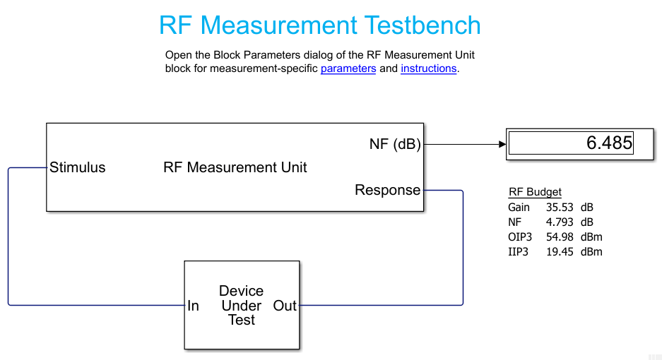
You can verify the harmonic balance NF, IP2 and IP3 results by exporting the budget to an RF Blockset testbench model using the following command:
exportTestbench(b)
To verify NF, double-click on the RF Measurement Unit to open the mask, then select NF from the Measured quantity pulldown. Then run the model. This verifies the Harmonic Balance NF calculation.

To verify IP2, double-click on the RF Measurement Unit to open its mask, then select IP2 from the Measured quantity pulldown.

Also uncheck the Simulate noise checkbox. Then run the model.

To verify IP3, select IP3 from the Measured quantity pulldown and run the model again.

Verifying HB results with RF Blockset Harmonic Balance
Rather than using the large machinery of circuit envelope and the RF Testbench, it is possible to build a simpler model that computes the IP2 and IP3 using two tones and harmonic balance. Open the model oipHB.slx found in the MATLAB/Examples folder. Simulate the model.
