Model Configuration Parameters for Radar Toolbox Support Package for Texas Instruments mmWave Radar Sensors
R2026bHardware Implementation Pane Overview
In the Modeling tab of the Simulink® Editor, click Model Settings.
In the Configuration Parameter dialog box, click Hardware Implementation.
Set the Hardware board parameter to a value, such as
TI Radar AWR1642BOOST (ARM Cortex - R4F).The parameter values under Hardware board settings are automatically populated to their default values.
You can optionally adjust these parameters for your particular use case.
Click Apply to apply the changes.
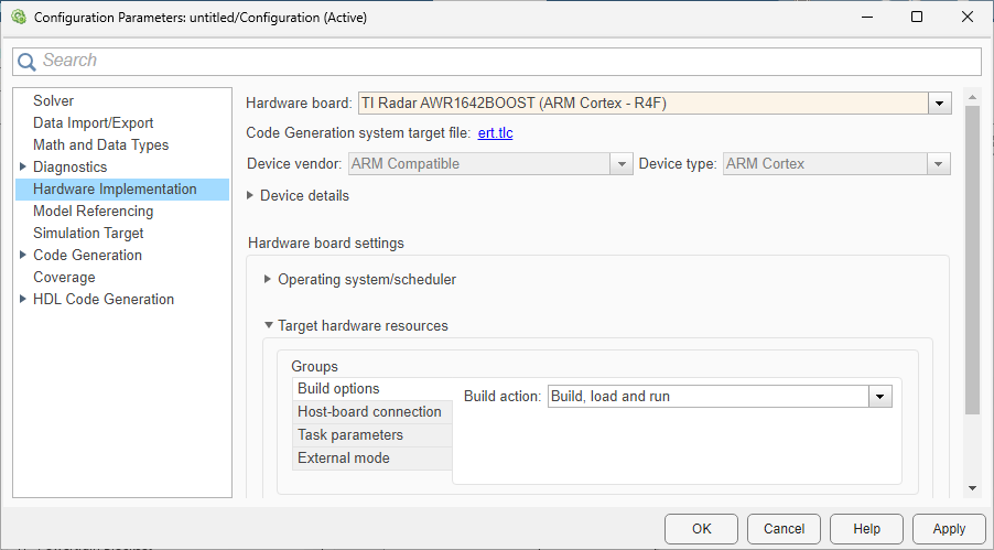
For more information on selecting a hardware support package and general configuration settings, see Hardware Implementation Pane (Simulink).
Build Options
| Parameter | Description | Default Value |
|---|---|---|
| Build Action | Option to specify whether you want only build or build, load, and run actions during code generation. |
|
Host-board connection
| Parameter | Description | Default Value |
|---|---|---|
| Specify Config Port | Automatically detect, manually select, or manually specify the COM port of your host computer to communicate with the TI mmWave radar board. |
Automatically
|
| Baud rate | Set baud rate of serial port when using External Mode, PIL, or Connected IO. | Depends on the selected radar board |
Task parameters
| Parameter | Description | Default Value |
|---|---|---|
| Stack size | Stack size |
16
|
Serial Properties: SCI Module A and SCI Module B
| Parameter | Description | Default Value |
|---|---|---|
| Baud rate (bits/s) | Set baud rate specific to the SCI module selected in the serial communication blocks. |
921600
|
| Number of data bits | Number of actual data bits transmitted per UART frame. | 8 |
| Parity mode | Type of parity used to detect transmission errors. | none |
| Number of stop bits | Number of Stop bits to indicate end of a packet. | 1 |
Connected IO
| Parameter | Description | Default Value |
|---|---|---|
| Connected IO mode | Select the Connected IO mode. |
Streaming
|
| Action on data discard for source blocks | Select the action required for data discard for source blocks. | warning |
External mode
| Parameter | Description | Default Value |
|---|---|---|
| Communication Interface | Options that you can select for the serial communication. | XCP on Serial |
| Run external mode in a background thread | Run external mode in a background thread. |
off
|
| Verbose | Option to view the External Mode execution progress and updates in the Diagnostic Viewer or in the MATLAB Command Window |
|
| Set logging buffer size automatically | Automatically set the number of bytes to preallocate for the buffer in the hardware during simulation. | on |
| Logging buffer size (in bytes) | Specify the memory buffer size for XCP-based External mode simulation | 2048 |

