URA Sum and Difference Monopulse
Sum-and-difference monopulse for URA
Libraries:
Phased Array System Toolbox /
Direction of Arrival
Description
The URA Sum-and-Difference Monopulse block estimates the direction of arrival of a narrowband signal on a uniform rectangular array (URA) based on an initial guess using a sum-and-difference monopulse algorithm. The block obtains the difference steering vector by phase-reversing the latter half of the sum steering vector.
Ports
Input
Output
Parameters
To edit block parameters interactively, use the Property Inspector. From the Simulink® Toolstrip, on the Simulation tab, in the Prepare gallery, select Property Inspector.
Array Parameters
Method to specify URA array, specified as Array (no subarrays)
or MATLAB expression.
Data Types: char | string
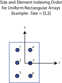
Size of a URA array, specified as a positive integer or 1-by-2 vector of positive integers.
If Array size is a 1-by-2 vector, the vector has the form
[NumberOfArrayRows,NumberOfArrayColumns].If Array size is an integer, the array has the same number of elements in each row and column.
For a URA, array elements are indexed from top to bottom along the
leftmost array column, and continued to the next columns from left to right. In this
figure, the Array size value of [3,2] creates an
array having three rows and two columns.
Dependencies
To enable this parameter, set Geometry to
URA.
MATLAB expression for creating an array, specified as a character vector or string.
Example: phased.URA(Size=[15,10])
Data Types: char | string
Sensor Array Tab: Element Parameters
Element Parameters
Dependencies
To enable this parameter, set Element type to Cardioid Antenna.
Coordinate system of custom antenna pattern, specified
az-el or phi-theta. When you
specify az-el, use the Azimuth angles
(deg) and Elevations angles (deg) parameters to
specify the coordinates of the pattern points. When you specify
phi-theta, use the Phi angles (deg)
and Theta angles (deg) parameters to specify the coordinates of the
pattern points.
Dependencies
To enable this parameter, set Element type to
Custom Antenna.
Phi angles of points at which to specify the antenna radiation pattern, specify as a real-valued 1-by-P row vector. P must be greater than 2. Angle units are in degrees. Phi angles must lie between 0° and 360° and be in strictly increasing order.
Dependencies
To enable this parameter, set the Element type parameter to
Custom Antenna and the Coordinate system of custom
antenna pattern parameter to
phi-theta.
Theta angles of points at which to specify the antenna radiation pattern, specify as a real-valued 1-by-Q row vector. Q must be greater than 2. Angle units are in degrees. Theta angles must lie between 0° and 360° and be in strictly increasing order.
Dependencies
To enable this parameter, set the Element type parameter to
Custom Antenna and the Coordinate system of custom
antenna pattern parameter to
phi-theta.
Align directions of the element normals to the direction of the array normal.
Dependencies
This parameter is enabled when Element type is set to
Custom Antenna.
Beamwidth of antenna pattern, specified as a 1-by-2 real-valued vector.
Dependencies
This parameter is enabled when Element type is set to
Gaussian Antenna.
Version History
Introduced in R2014b