Obtain range-angle response map for array
Phased Array System Toolbox / Detection
The Range-Angle Response block computes the range-angle map of an input signal. The output response is a matrix or a three-dimensional array whose rows represent range gates and columns represent angles. Pages represent
X
— Input signal data cubeInput signal cube, specified as a complex-valued K-by-N matrix or complex-valued K-by-N-by-L array. The contents of the data cube depend on the type of range-angle processing specified by the different syntaxes.
K is the number of fast-time or range samples.
N is the number of independent spatial channels such as sensors or directions.
L is the slow-time dimension that corresponds to the number of pulses or sweeps in the input signal.
The size of the first dimension of the input matrix can vary to simulate a changing signal length. A size change can occur, for example, in the case of a pulse waveform with variable pulse repetition frequency.
PRF
— Pulse repetition frequencyPulse repetition frequency
To enable this input argument, set the value of Range
processing method to FFT
and do not select the Dechirp input signal
check box.
Data Types: double
Xref
— Reference signal used for dechirpingReference signal used for dechirping, specified as a complex-valued
K-by-1 column vector. The number of rows must
equal the length of the fast-time dimension of
X
.
To enable this input argument, set the value of Range
processing method to FFT
and select the Dechirp input signal check
box.
Data Types: double
Complex Number Support: Yes
Coeff
— Matched filter coefficientsMatched filter coefficients, specified as a complex-valued P-by-1 column vector. P must be less than or equal to K. K is the number of fast-time or range sample.
To enable this input argument, set the value of Range
processing method to Matched
filter
.
Data Types: double
Complex Number Support: Yes
El
— Elevation angleElevation angle of response, specified as a scalar between –90° and +90°. The range-angle response is computed for this elevation. Units are in degrees.
To enable this argument, set the Source of elevation
angle parameter to Input
port
.
Data Types: double
Resp
— Range response data cubeRange response data cube, returned as one of the following:
Complex-valued M-element column vector
Complex-valued M-by-L matrix
Complex-valued M-by-N by-L array
The value of M depends on the type of processing
Range Processing Method | Value of M |
---|---|
FFT | If you set the Source of FFT
length in range processing parameter to
|
Matched filter | M = K, the length of the
fast-time dimension of
X . |
Data Types: double
Complex Number Support: Yes
Range
— Range values along range dimensionRange values along range dimension, returned as a real-valued
M-by-1 column vector. This vector defines the
ranges that correspond to the fast-time dimension of the
RESP
output data cube. M is
the length of the fast-time dimension of RESP
.
Range values are monotonically increasing and equally spaced. Units are
in meters.
Data Types: double
Ang
— Angle values along angle directionAngle values corresponding to the samples along angle direction, returned as a P-by-1 real-valued vector. Units are in degrees.
Data Types: double
Signal propagation speed (m/s)
— Signal propagation speedphysconst('LightSpeed')
(default) | real-valued positive scalarSignal propagation speed, specified as a real-valued positive scalar. The default value of the
speed of light is the value returned by physconst('LightSpeed')
.
Units are in meters per second.
Example: 3e8
Data Types: double
Operating frequency (Hz)
— System operating frequency3.0e8
(default) | positive real scalarSystem operating frequency, specified as a positive scalar. Units are in Hz.
Range processing method
— Range processing methodMatched filter
(default) | FFT
Range processing method, specified as Matched
filter
or FFT
.
Matched filter
— The object
match-filters the incoming signal. This approach is commonly used
for pulsed signals, where the matched filter is the time reverse of
the transmitted signal.
FFT
— The object applies an FFT
to the input signal. This approach is commonly used for chirped
signals such as FMCW and linear FM pulsed signals.
Data Types: char
Inherit sample rate
— Inherit sample rate from upstream blocksSelect this parameter to inherit the sample rate from upstream blocks. Otherwise, specify the sample rate using the Sample rate (Hz) parameter.
Data Types: Boolean
Sample rate (Hz)
— Sampling rate of signal1e6
(default) | positive real-valued scalarSpecify the signal sampling rate as a positive scalar. Units are in Hz.
To enable this parameter, clear the Inherit sample rate check box.
Data Types: double
FM sweep slope (Hz/s)
— Linear FM sweep slope1.0e9
(default) | scalarLinear FM sweep slope, specified as a scalar. The fast-time dimension of
the X
input port must correspond to sweeps having this
slope.
Example: 1.5e9
To enable this parameter, set the Range processing
method parameter to
FFT
.
Data Types: double
Dechirp input signal
— Enable dechirping of input signalson
(default) | off
Option to enable dechirping of input signals, specified as
on
or off
. Not selecting this
check box indicates that the input signal is already dechirped and no
dechirp operation is necessary. Select this check box when the input signal
requires dechirping.
To enable this parameter, set the Range processing
method parameter to
FFT
.
Data Types: Boolean
Source of FFT length in range
— Source of FFT length for range processing of dechirped signalsAuto
(default) | Property
Source of the FFT length used for the range processing of dechirped
signals, specified as Auto
or
Property
.
Auto
— The FFT length equals
the length of the fast-time dimension of the input data
cube.
Property
— Specify the FFT
length by using the FFT length in range
processing parameter.
To enable this parameter, set the Range processing
method parameter to
FFT
.
Data Types: char
FFT length in range processing
— FFT length used for range processing1024
(default) | positive integerFFT length used for range processing, specified as a positive integer.
To enable this parameter, set the Range processing
method parameter to FFT
and
the Source of FFT length in range processing
parameter to Property
.
Data Types: double
Range processing window
— FFT weighting window for range processingNone
(default) | Hamming
| Chebyshev
| Hann
| Kaiser
| Taylor
FFT weighting window for range processing, specified as
None
, Hamming
,
Chebyshev
, Hann
,
Kaiser
, or
Taylor
.
If you set this parameter to Taylor
, the
generated Taylor window has four nearly constant sidelobes next to the
mainlobe.
To enable this parameter, set the Range processing
method parameter to
FFT
.
Data Types: char
Range sidelobe attenuation level
— Sidelobe attenuation for range processing30
(default) | scalarSidelobe attenuation for range processing, specified as a positive scalar. This attenuation applies only to Kaiser, Chebyshev, or Taylor windows. Units are in dB.
To enable this parameter, set the Range processing
method parameter to FFT
and
the Range processing window parameter to
Kaiser
,
Chebyshev
, or
Kaiser
.
Set reference range at center
— Set reference range at center of range gridon
(default) | off
Set reference range at center of range grid, specified as
on
or off
. Selecting this check
box enables you to set the reference range at the center of the range grid.
Otherwise, the reference range corresponds to the beginning of the range
grid.
To enable this parameter, set the Range processing
method to FFT
.
Data Types: Boolean
Reference range (m)
— Reference range of range grid0.0
(default) | nonnegative scalarReference range of the range grid, specified as a nonnegative scalar.
If you set the Range processing method
parameter to 'Matched filter'
, the reference
range is set to the start of the range grid.
If you set the Range processing method
parameter to FFT
, the reference range
is determined by the Set reference range at
center parameter.
When you select the Set reference range at center check box, the reference range is set to the center of the range grid.
Otherwise, the reference range is set to the start of the range grid.
Units are in meters.
Example: 1000.0
Data Types: double
Source of elevation angle
— Source of elevation angleProperty
(default) | Input portSource of elevation angle, specified as
Property
or Input
port.
Property | The elevation angle comes from the Elevation angle (deg) parameter. |
Input port | The elevation angle comes from an input port. |
Elevation angle (deg)
— Elevation angle used to calculate range-angle response0
(default) | scalarElevation angle used to calculate range-angle response, specified as a
scalar. The angle must be between --90 and 90 degrees. This property applies
when you set the ElevationAngleSource property to
'Property'
. The default value of this property is
0.
Angle span (deg)
— Angle response span[-90 90]
(default) | real-valued 1-by-2 vectorAngle response span, specified as a real-valued 2-by-1 vector. The object
calculates the range-angle response within the angle range,
[min_angle max_angle]
.
Example: [-45 45]
Data Types: 12wqqqq`
| qdouble
Number of angle bins
— Number of samples in angle spanNumber of samples in angle span used to calculate range-angle response, specified as a positive integer greater than two.
Example: [256]
Data Types: double
Simulate using
— Block simulation methodInterpreted Execution
(default) | Code Generation
Block simulation, specified as Interpreted Execution
or Code
Generation
. If you want your block to use the MATLAB® interpreter,
choose Interpreted Execution
. If you want
your block to run as compiled code, choose Code Generation
.
Compiled code requires time to compile but usually runs faster.
Interpreted execution is useful when you are developing and tuning a model. The block runs the
underlying System object™ in MATLAB. You can change and execute your model quickly. When you are satisfied
with your results, you can then run the block using Code
Generation
. Long simulations run faster with generated code than in
interpreted execution. You can run repeated executions without recompiling, but if you
change any block parameters, then the block automatically recompiles before
execution.
This table shows how the Simulate using parameter affects the overall simulation behavior.
When the Simulink® model is in Accelerator
mode, the block mode specified
using Simulate using overrides the simulation mode.
Acceleration Modes
Block Simulation | Simulation Behavior | ||
Normal | Accelerator | Rapid Accelerator | |
Interpreted Execution | The block executes using the MATLAB interpreter. | The block executes using the MATLAB interpreter. | Creates a standalone executable from the model. |
Code Generation | The block is compiled. | All blocks in the model are compiled. |
For more information, see Choosing a Simulation Mode (Simulink).
Specify sensor array as
— Method to specify arrayArray (no subarrays)
(default) | Partitioned array
| Replicated subarray
| MATLAB expression
Method to specify array, specified as Array (no
subarrays)
or MATLAB expression
.
Array (no subarrays)
—
use the block parameters to specify the array.
Partitioned array
—
use the block parameters to specify the array.
Replicated subarray
—
use the block parameters to specify the array.
MATLAB expression
—
create the array using a MATLAB expression.
Expression
— MATLAB expression used to create an arrayMATLAB expression used to create an array, specified as a valid Phased Array System Toolbox array System object.
Example: phased.URA('Size',[5,3])
To enable this parameter, set Specify sensor array
as to MATLAB expression
.
Element type
— Array element typesIsotropic Antenna
(default) | Cosine Antenna
| Custom Antenna
| Omni Microphone
| Custom Microphone
Antenna or microphone type, specified as one of the following:
Isotropic Antenna
Cosine Antenna
Custom Antenna
Omni Microphone
Custom Microphone
Operating frequency range (Hz)
— Operating frequency range of the antenna or microphone element[0,1.0e20]
(default) | real-valued 1-by-2 row vectorSpecify the operating frequency range of the antenna or microphone
element as a 1-by-2 row vector in the form [LowerBound,UpperBound]
.
The element has no response outside this frequency range. Frequency
units are in Hz.
To enable this parameter, set Element type to Isotropic
Antenna
, Cosine Antenna
, or Omni
Microphone
.
Operating frequency vector (Hz)
— Operating frequency range of custom antenna or microphone elements[0,1.0e20]
(default) | real-valued row vectorSpecify the frequencies at which to set antenna and microphone frequency responses as a 1-by-L row vector of increasing real values. The antenna or microphone element has no response outside the frequency range specified by the minimum and maximum elements of this vector. Frequency units are in Hz.
To enable this parameter, set Element type to Custom
Antenna
or Custom Microphone
. Use Frequency
responses (dB) to set the responses at these frequencies.
Baffle the back of the element
— Set back response of an Isotropic Antenna
element or an Omni Microphone
element to zeroSelect this check box to baffle the back response of the element. When back baffled, the responses at all azimuth angles beyond ±90° from broadside are set to zero. The broadside direction is defined as 0° azimuth angle and 0° elevation angle.
To enable this check box, set Element type to Isotropic
Antenna
or Omni Microphone
.
Exponent of cosine pattern
— Exponents of azimuth and elevation cosine patterns[1.5 1.5]
(default) | nonnegative scalar | real-valued 1-by-2 matrix of nonnegative valuesSpecify the exponents of the cosine pattern as a nonnegative scalar or a real-valued 1-by-2 matrix of nonnegative values. When Exponent of cosine pattern is a 1-by-2 vector, the first element is the exponent in the azimuth direction and the second element is the exponent in the elevation direction. When you set this parameter to a scalar, both the azimuth direction and elevation direction cosine patterns are raised to the same power.
To enable this parameter, set Element type to Cosine
Antenna
.
Frequency responses (dB)
— Antenna and microphone frequency response[0,0]
(default) | real-valued row vectorFrequency response of a custom antenna or custom microphone for the frequencies defined by the Operating frequency vector (Hz) parameter. The dimensions of Frequency responses (dB) must match the dimensions of the vector specified by the Operating frequency vector (Hz) parameter.
To enable this parameter, set Element type to Custom
Antenna
or Custom Microphone
.
Input Pattern Coordinate System
— Coordinate system of custom antenna patternaz-el
(default) | phi-theta
Coordinate system of custom antenna pattern, specified az-el
or phi-theta
. When you specify az-el
, use the Azimuth angles (deg) and Elevations angles (deg) parameters to specify the coordinates of the pattern points. When you specify phi-theta
, use the Phi angles (deg) and Theta angles (deg) parameters to specify the coordinates of the pattern points.
To enable this parameter, set Element type to Custom Antenna
.
Azimuth angles (deg)
— Azimuth angles of antenna radiation pattern [-180:180]
(default) | real-valued row vectorSpecify the azimuth angles at which to calculate the antenna radiation pattern as a 1-by-P row vector. P must be greater than 2. Azimuth angles must lie between –180° and 180°, inclusive, and be in strictly increasing order.
To enable this parameter, set the Element type parameter to
Custom Antenna
and the Input Pattern Coordinate
System parameter to az-el
.
Elevation angles (deg)
— Elevation angles of antenna radiation pattern[-90:90]
(default) | real-valued row vectorSpecify the elevation angles at which to compute the radiation pattern as a 1-by-Q vector. Q must be greater than 2. Angle units are in degrees. Elevation angles must lie between –90° and 90°, inclusive, and be in strictly increasing order.
To enable this parameter, set the Element type parameter to
Custom Antenna
and the Input Pattern Coordinate
System parameter to az-el
.
Phi Angles (deg)
— Phi angle coordinates of custom antenna radiation pattern0:360
| real-valued 1-by-P row vectorPhi angles of points at which to specify the antenna radiation pattern, specify as a real-valued 1-by-P row vector. P must be greater than 2. Angle units are in degrees. Phi angles must lie between 0° and 360° and be in strictly increasing order.
To enable this parameter, set the Element type parameter to Custom Antenna
and the Input Pattern Coordinate System parameter to phi-theta
.
Theta Angles (deg)
— Theta angle coordinates of custom antenna radiation pattern0:180
| real-valued 1-by-Q row vectorTheta angles of points at which to specify the antenna radiation pattern, specify as a real-valued 1-by-Q row vector. Q must be greater than 2. Angle units are in degrees. Theta angles must lie between 0° and 360° and be in strictly increasing order.
To enable this parameter, set the Element type parameter to Custom Antenna
and the Input Pattern Coordinate System parameter to phi-theta
.
Magnitude pattern (dB)
— Magnitude of combined antenna radiation patternzeros(181,361)
(default) | real-valued Q-by-P matrix | real-valued Q-by-P-by-L arrayMagnitude of the combined antenna radiation pattern, specified as a Q-by-P matrix or a Q-by-P-by-L array.
When the Input Pattern Coordinate System parameter is
set to az-el
, Q equals the
length of the vector specified by the Elevation angles
(deg) parameter and P equals the length of
the vector specified by the Azimuth angles (deg)
parameter.
When the Input Pattern Coordinate System parameter is
set to phi-theta
, Q equals the
length of the vector specified by the Theta Angles
(deg) parameter and P equals the length of
the vector specified by the Phi Angles (deg)
parameter.
The quantity L equals the length of the Operating frequency vector (Hz).
If this parameter is a Q-by-P matrix, the same pattern is applied to all frequencies specified in the Operating frequency vector (Hz) parameter.
If the value is a Q-by-P-by-L array, each Q-by-P page of the array specifies a pattern for the corresponding frequency specified in the Operating frequency vector (Hz) parameter.
To enable this parameter, set Element type to
Custom Antenna
.
Phase pattern (deg)
— Custom antenna radiation phase patternzeros(181,361)
(default) | real-valued Q-by-P matrix | real-valued Q-by-P-by-L arrayPhase of the combined antenna radiation pattern, specified as a Q-by-P matrix or a Q-by-P-by-L array.
When the Input Pattern Coordinate System parameter is
set to az-el
, Q equals the
length of the vector specified by the Elevation angles
(deg) parameter and P equals the length of
the vector specified by the Azimuth angles (deg)
parameter.
When the Input Pattern Coordinate System parameter is
set to phi-theta
, Q equals the
length of the vector specified by the Theta Angles
(deg) parameter and P equals the length of
the vector specified by the Phi Angles (deg)
parameter.
The quantity L equals the length of the Operating frequency vector (Hz).
If this parameter is a Q-by-P matrix, the same pattern is applied to all frequencies specified in the Operating frequency vector (Hz) parameter.
If the value is a Q-by-P-by-L array, each Q-by-P page of the array specifies a pattern for the corresponding frequency specified in the Operating frequency vector (
To enable this parameter, set Element type to
Custom Antenna
.
MatchArrayNormal
— Rotate antenna element to array normalon
(default) | off
Select this check box to rotate the antenna element pattern to align with the array normal. When not selected, the element pattern is not rotated.
When the antenna is used in an antenna array and the Input Pattern Coordinate System parameter is az-el
, selecting this check box rotates the pattern so that the x-axis of the element coordinate system points along the array normal. Not selecting uses the element pattern without the rotation.
When the antenna is used in an antenna array and Input Pattern Coordinate System is set to phi-theta
, selecting this check box rotates the pattern so that the z-axis of the element coordinate system points along the array normal.
Use the parameter in conjunction with the Array normal parameter of the URA
and UCA
arrays.
To enable this parameter, set Element type to Custom Antenna
.
Polar pattern frequencies (Hz)
— Polar pattern microphone response frequenciesPolar pattern microphone response frequencies, specified as a real scalar, or a real-valued, 1-by-L vector. The response frequencies lie within the frequency range specified by the Operating frequency vector (Hz) vector.
To enable this parameter, set Element type set to
Custom Microphone
.
Polar pattern angles (deg)
— Polar pattern response angles[-180:180]
(default) | real-valued -by-P row vectorSpecify the polar pattern response angles, as a 1-by-P vector. The angles are measured from the central pickup axis of the microphone and must be between –180° and 180°, inclusive.
To enable this parameter, set Element type to Custom
Microphone
.
Polar pattern (dB)
— Custom microphone polar responsezeros(1,361)
(default) | real-valued L-by-P matrixSpecify the magnitude of the custom microphone element polar patterns as an L-by-P matrix. L is the number of frequencies specified in Polar pattern frequencies (Hz). P is the number of angles specified in Polar pattern angles (deg). Each row of the matrix represents the magnitude of the polar pattern measured at the corresponding frequency specified in Polar pattern frequencies (Hz) and all angles specified in Polar pattern angles (deg). The pattern is measured in the azimuth plane. In the azimuth plane, the elevation angle is 0° and the central pickup axis is 0° degrees azimuth and 0° degrees elevation. The polar pattern is symmetric around the central axis. You can construct the microphone response pattern in 3-D space from the polar pattern.
To enable this parameter, set Element type to Custom
Microphone
.
Geometry
— Array geometryULA
(default) | URA
| UCA
| Conformal Array
Array geometry, specified as one of
ULA
— Uniform linear
array
URA
— Uniform rectangular
array
UCA
— Uniform circular
array
Conformal Array
—
arbitrary element positions
Number of elements
— Number of array elements2
for ULA arrays and 5
for
UCA arrays (default) | integer greater than or equal to 2The number of array elements for ULA or UCA arrays, specified as an integer greater than or equal to 2.
When you set Specify sensor array as to Replicated
subarray
, this parameter applies to each subarray.
To enable this parameter, set Geometry to ULA
or UCA
.
Element spacing (m)
— Spacing between array elements0.5
for ULA arrays and [0.5,0.5]
for
URA arrays (default) | positive scalar for ULA or URA arrays | 2-element vector of positive values for URA arraysSpacing between adjacent array elements:
ULA — specify the spacing between two adjacent elements in the array as a positive scalar.
URA — specify the spacing as a positive scalar
or a 1-by-2 vector of positive values. If Element spacing
(m) is a scalar, the row and column spacings are equal.
If Element spacing (m) is a vector, the vector
has the form [SpacingBetweenArrayRows,SpacingBetweenArrayColumns]
.
When you set Specify sensor array as to Replicated
subarray
, this parameter applies to each subarray.
To enable this parameter, set Geometry to ULA
or URA
.
Array axis
— Linear axis direction of ULAy
(default) | x
| z
Linear axis direction of ULA, specified as y
, x
,
or z
. All ULA array elements are uniformly
spaced along this axis in the local array coordinate system.
To enable this parameter, set Geometry to
ULA
.
This parameter is also enabled when the block only supports ULA arrays.
Array size
— Dimensions of URA array[2,2]
(default) | positive integer | 1-by-2 vector of positive integers
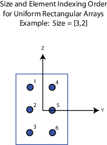
Dimensions of a URA array, specified as a positive integer or 1-by-2 vector of positive integers.
If Array size is a 1-by-2 vector, the vector has the
form [NumberOfArrayRows,NumberOfArrayColumns]
.
If Array size is an integer, the array has the same number of rows and columns.
When you set Specify sensor array as to
Replicated subarray
, this parameter applies to each
subarray.
For a URA, array elements are indexed from top to bottom along the
leftmost column, and then continue to the next columns from left to right. In this
figure, the Array size value of [3,2]
creates an
array having three rows and two columns.
To enable this parameter, set Geometry to URA
.
Element lattice
— Lattice of URA element positionsRectangular
(default) | Triangular
Lattice of URA element positions, specified as Rectangular
or Triangular
.
Rectangular
— Aligns
all the elements in row and column directions.
Triangular
— Shifts
the even-row elements of a rectangular lattice toward the positive
row-axis direction. The displacement is one-half the element spacing
along the row dimension.
To enable this parameter, set Geometry to URA
.
Array normal
— Array normal directionx
for URA arrays
or z
for UCA arrays (default) | y
Array normal direction, specified as x
, y
,
or z
.
Elements of planar arrays lie in a plane orthogonal to the selected array normal direction. Element boresight directions point along the array normal direction.
Array Normal Parameter Value | Element Positions and Boresight Directions |
---|---|
x | Array elements lie in the yz-plane. All element boresight vectors point along the x-axis. |
y | Array elements lie in the zx-plane. All element boresight vectors point along the y-axis. |
z | Array elements lie in the xy-plane. All element boresight vectors point along the z-axis. |
To enable this parameter, set Geometry to URA
or UCA
.
Radius of UCA (m)
— UCA array radiusRadius of UCA array, specified as a positive scalar.
To enable this parameter, set Geometry to UCA
.
Element positions (m)
— Positions of conformal array elements[0;0;0]
(default) | 3-by-Nmatrix of real valuesPositions of the elements in a conformal array, specified as
a 3-by-N matrix of real values, where N is
the number of elements in the conformal array. Each column of this
matrix represents the position [x;y;z]
of an array
element in the array local coordinate system. The origin of the local
coordinate system is (0,0,0). Units are in meters.
When you set Specify sensor array as to Replicated
subarray
, this parameter applies to each subarray.
To enable this parameter set Geometry to Conformal
Array
.
Element normals (deg)
— Direction of conformal array element normal vectors[0;0]
| 2-by-1 column vector | 2-by-N matrixDirection of element normal vectors in a conformal array, specified as a 2-by-1 column vector
or a 2-by-N matrix. N indicates the number of
elements in the array. For a matrix, each column specifies the normal direction of the
corresponding element in the form [azimuth;elevation]
with respect to
the local coordinate system. The local coordinate system aligns the positive
x-axis with the direction normal to the conformal array. If the
parameter value is a 2-by-1 column vector, the same pointing direction is used for all
array elements.
When you set Specify sensor array as to Replicated
subarray
, this parameter applies to each subarray.
You can use the Element positions (m) and Element normals (deg) parameters to represent any arrangement in which pairs of elements differ by certain transformations. The transformations can combine translation, azimuth rotation, and elevation rotation. However, you cannot use transformations that require rotation about the normal direction.
To enable this parameter, set Geometry to Conformal
Array
.
Taper
— Array element tapersElement tapering, specified as a complex-valued scalar or a complex-valued 1-by-N row vector. In this vector, N represents the number of elements in the array.
Also known as element weights, tapers multiply the array element responses. Tapers modify both amplitude and phase of the response to reduce side lobes or steer the main response axis.
If Taper is a scalar, the same weight is applied to each element. If Taper is a vector, a weight from the vector is applied to the corresponding sensor element. The number of weights must match the number of elements of the array.
When you set Specify sensor array as to Replicated
subarray
, this parameter applies to each subarray.
Subarray definition matrix
— Define elements belonging to subarraysSpecify the subarray selection as an M-by-N matrix. M is the number of subarrays and N is the total number of elements in the array. Each row of the matrix represents a subarray and each entry in the row indicates when an element belongs to the subarray. When the entry is zero, the element does not belong the subarray. A nonzero entry represents a complex-valued weight applied to the corresponding element. Each row must contain at least one nonzero entry.
The phase center of each subarray lies at the subarray geometric center. The subarray geometric center depends on the Subarray definition matrix and Geometry parameters.
To enable this parameter, set Specify sensor array as to
Partitioned array
.
Subarray steering method
— Specify subarray steering methodNone
(default) | Phase
| Time
Subarray steering method, specified as one of
None
Phase
Time
Custom
Selecting Phase
or Time
opens the
Steer
input port on the Narrowband Receive Array,
Narrowband Transmit Array, Wideband Receive Array,
Wideband Transmit Array blocks, Constant Gamma
Clutter, and GPU Constant Gamma Clutter blocks.
Selecting Custom
opens the WS
input port on the
Narrowband Receive Array, Narrowband Transmit Array,
Wideband Receive Array, Wideband Transmit Array
blocks, Constant Gamma Clutter, and GPU Constant Gamma
Clutter blocks.
To enable this parameter, set Specify sensor array as to
Partitioned array
or Replicated
subarray
.
Phase shifter frequency (Hz)
— Subarray phase shifting frequency3.0e8
(default) | positive real-valued scalarOperating frequency of subarray steering phase shifters, specified as a positive real-valued scalar. Units are Hz.
To enable this parameter, set Sensor array to Partitioned
array
or Replicated subarray
and set Subarray
steering method to Phase
.
Number of bits in phase shifters
— Subarray steering phase shift quantization bits0
(default) | non-negative integerSubarray steering phase shift quantization bits, specified as a non-negative integer. A value of zero indicates that no quantization is performed.
To enable this parameter, set Sensor array to Partitioned
array
or Replicated subarray
and set Subarray
steering method to Phase
.
Subarrays layout
— Subarray position specificationRectangular
(default) | Custom
Specify the layout of replicated subarrays as Rectangular
or Custom
.
When you set this parameter to Rectangular
,
use the Grid size and Grid spacing parameters
to place the subarrays.
When you set this parameter to Custom
,
use the Subarray positions (m) and Subarray
normals parameters to place the subarrays.
To enable this parameter, set Sensor array to Replicated
subarray
Grid size
— Dimensions of rectangular subarray grid[1,2]
(default)
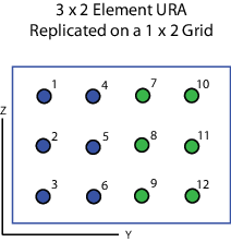
Rectangular subarray grid size, specified as a single positive integer, or a 1-by-2 row vector of positive integers.
If Grid size is an integer scalar, the
array has an equal number of subarrays in each row and column. If Grid
size is a 1-by-2 vector of the form [NumberOfRows,
NumberOfColumns]
, the first entry is the number of subarrays
along each column. The second entry is the number of subarrays in
each row. A row is along the local y-axis, and
a column is along the local z-axis. The figure
here shows how you can replicate a 3-by-2 URA subarray using a Grid
size of [1,2]
.
To enable this parameter, set Sensor array to Replicated
subarray
and Subarrays layout to Rectangular
.
Grid spacing (m)
— Spacing between subarrays on rectangular gridAuto
(default) | positive real-valued scalar | 1-by-2 vector of positive real-valuesThe rectangular grid spacing of subarrays, specified as a positive,
real-valued scalar, a 1-by-2 row vector of positive, real-values,
or Auto
. Units are in meters.
If Grid spacing is a scalar, the spacing along the row and the spacing along the column is the same.
If Grid spacing is a 1-by-2
row vector, the vector has the form [SpacingBetweenRows,SpacingBetweenColumn]
.
The first entry specifies the spacing between rows along a column.
The second entry specifies the spacing between columns along a row.
If Grid spacing is set to Auto
,
replication preserves the element spacing of the subarray for both
rows and columns while building the full array. This option is available
only when you specify Geometry as ULA
or URA
.
To enable this parameter, set Sensor array to Replicated
subarray
and Subarrays layout to Rectangular
.
Subarray positions (m)
— Positions of subarrays[0,0;0.5,0.5;0,0]
(default) | 3-by-N real-valued matrixPositions of the subarrays in the custom grid, specified as
a real 3-by-N matrix, where N is
the number of subarrays in the array. Each column of the matrix represents
the position of a single subarray in the array local coordinate system.
The coordinates are expressed in the form [x; y; z]
.
Units are in meters.
To enable this parameter, set Sensor array to Replicated
subarray
and Subarrays layout to Custom
.
Subarray normals
— Direction of subarray normal vectors[0,0;0,0]
(default) | 2-by-N real matrixSpecify the normal directions of the subarrays in the array.
This parameter value is a 2-by-N matrix, where N is
the number of subarrays in the array. Each column of the matrix specifies
the normal direction of the corresponding subarray, in the form [azimuth;elevation]
.
Angle units are in degrees. Angles are defined with respect to the
local coordinate system.
You can use the Subarray positions and Subarray normals parameters to represent any arrangement in which pairs of subarrays differ by certain transformations. The transformations can combine translation, azimuth rotation, and elevation rotation. However, you cannot use transformations that require rotation about the normal.
To enable this parameter, set the Sensor array parameter
to Replicated subarray
and the Subarrays
layout to Custom
.
You clicked a link that corresponds to this MATLAB command:
Run the command by entering it in the MATLAB Command Window. Web browsers do not support MATLAB commands.
Choose a web site to get translated content where available and see local events and offers. Based on your location, we recommend that you select: .
Select web siteYou can also select a web site from the following list:
Select the China site (in Chinese or English) for best site performance. Other MathWorks country sites are not optimized for visits from your location.