Beamforming for MIMO-OFDM Systems
This example shows how to model a point-to-point MIMO-OFDM system with beamforming. The combination of multiple-input-multiple-output (MIMO) and orthogonal frequency division multiplexing (OFDM) techniques have been adopted in recent wireless standards, such as 802.11x families, to provide higher data rate. Because MIMO uses antenna arrays, beamforming can be adopted to improve the received signal to noise ratio (SNR) which in turn reduces the bit error rate (BER).
This example requires Communications Toolbox™.
Introduction
The term MIMO is used to describe a system where multiple transmitters or multiple receivers are present. In practice the system can take many different forms, such as single-input-multiple-output (SIMO) or multiple-input-single-output (MISO) system. This example illustrates a downlink MISO system. An 8-element ULA is deployed at the base station as the transmitter while the mobile unit is the receiver with a single antenna.
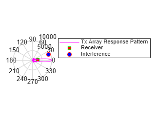
The rest of the system is configured as follows. The transmitter power is 9 watts and the transmit gain is -8 dB. The mobile receiver is stationary and located at 2750 meters away, and is 3 degrees off the transmitter's boresight. An interferer with a power of 1 watt and a gain of -20 dB is located at 9000 meters, 20 degrees off the transmitter's boresight.
% Initialize system constants
rng(2014);
gc = helperGetDesignSpecsParameters();

% Tunable parameters
tp.txPower = 9;           % watt
tp.txGain = -8;           % dB
tp.mobileRange = 2750;    % m
tp.mobileAngle = 3;       % degrees
tp.interfPower = 1;       % watt
tp.interfGain = -20;      % dB
tp.interfRange = 9000;    % m
tp.interfAngle =   20;    % degrees
tp.numTXElements = 8;
tp.steeringAngle = 0;     % degrees
tp.rxGain = 108.8320 - tp.txGain; % dB

numTx= tp.numTXElements;
The entire scene can be depicted in the figure below.
helperPlotMIMOEnvironment(gc, tp);
Signal Transmission
First, configure the system's transmitter.
[encoder,scrambler,modulatorOFDM,steeringvec,transmitter,...
    radiator,pilots,numDataSymbols,frmSz] = helperMIMOTxSetup(gc,tp);
There are many components in the transmitter subsystem, such as the convolutional encoder, the scrambler, the QAM modulator, the OFDM modulator, and so on. The message is first converted to an information bit stream and then passed through source coding and modulation stages to prepare for the radiation.
txBits = randi([0, 1], frmSz,1);
coded = encoder(txBits);
bitsS = scrambler(coded);
tx = qammod(bitsS,gc.modMode,'InputType','bit','UnitAveragePower',true);
In an OFDM system, the data is carried by multiple sub-carriers that are orthogonal to each other.
ofdm1 = reshape(tx, gc.numCarriers,numDataSymbols);
Then, the data stream is duplicated to all radiating elements in the transmitting array
ofdmData = repmat(ofdm1,[1, 1, numTx]);
txOFDM = modulatorOFDM(ofdmData, pilots);
%scale
txOFDM = txOFDM * ...
    (gc.FFTLength/sqrt(gc.FFTLength-sum(gc.NumGuardBandCarriers)-1));

% Amplify to achieve peak TX power for each channel
for n = 1:numTx
    txOFDM(:,n) = transmitter(txOFDM(:,n));
end
In a MIMO system, it is also possible to separate multiple users spatial division multiplexing (SDMA). In these situations, the data stream is often modulated by a weight corresponding to the desired direction so that once radiated, the signal is maximized in that direction. Because in a MIMO channel, the signal radiated from different elements in an array may go through different propagation environments, the signal radiated from each antenna should be propagated individually. This can be achieved by setting CombineRadiatedSignals to false on the phased.Radiator component.
radiator.CombineRadiatedSignals = false;
To achieve precoding, the data stream radiated from each antenna in the array is modulated by a phase shift corresponding to its radiating direction. The goal of this precoding is to ensure these data streams add in phase if the array is steered toward that direction. Precoding can be specified as weights used at the radiator.
wR = steeringvec(gc.fc,[-tp.mobileAngle;0]);
Meanwhile, the array is also steered toward a given steering angle, so the total weights are a combination of both precoding and the steering weights.
wT = steeringvec(gc.fc,[tp.steeringAngle;0]);
weight = wT.* wR;
The transmitted signal is thus given by
txOFDM = radiator(txOFDM,repmat([tp.mobileAngle;0],1,numTx),conj(weight));
Note that the transmitted signal, txOFDM, is a matrix whose columns represent data streams radiated from the corresponding elements in the transmit array.
Signal Propagation
Next, the signal propagates through a MIMO channel. In general, there are two propagation effects on the received signal strength that are of interest: one of them is the spreading loss due to the propagation distance, often termed as the free space path loss; and the other is the fading due to multipath. This example models both effects.
[channel,interferenceTransmitter,toRxAng,spLoss] = ...
    helperMIMOEnvSetup(gc,tp);
[sigFade, chPathG] =  channel(txOFDM);
sigLoss = sigFade/sqrt(db2pow(spLoss(1)));
To simulate a more realistic mobile environment, the next section also inserts an interference source. Note that in a wireless communication system, the interference is often a different mobile user.
% Generate interference and apply gain and propagation loss
numBits = size(sigFade,1);
interfSymbols = wgn(numBits,1,1,'linear','complex');
interfSymbols = interferenceTransmitter(interfSymbols);
interfLoss = interfSymbols/sqrt(db2pow(spLoss(2)));
Signal Reception
The receiving antenna collects both the propagated signal as well as the interference and passes them to the receiver to recover the original information embedded in the signal. Just like the transmit end of the system, the receiver used in a MIMO-OFDM system also contains many stages, including OFDM demodulator, QAM demodulator, descrambler, equalizer, and Viterbi decoder.
[collector,receiver,demodulatorOFDM,descrambler,decoder] = ...
    helperMIMORxSetup(gc,tp,numDataSymbols);

rxSig = collector([sigLoss interfLoss],toRxAng);

% Front-end amplifier gain and thermal noise
rxSig = receiver(rxSig);

rxOFDM = rxSig * ...
    (sqrt(gc.FFTLength-sum(gc.NumGuardBandCarriers)-1)) / (gc.FFTLength);

% OFDM Demodulation
rxOFDM = demodulatorOFDM(rxOFDM);

% Channel estimation
hD = helperIdealChannelEstimation(gc,  numDataSymbols, chPathG);

% Equalization
rxEq = helperEqualizer(rxOFDM, hD, numTx);

% Collapse OFDM matrix
rxSymbs = rxEq(:);

rxBitsS = qamdemod(rxSymbs,gc.modMode,'UnitAveragePower',true,...
    'OutputType','bit');
rxCoded = descrambler(rxBitsS);
rxDeCoded = decoder(rxCoded);
rxBits = rxDeCoded(1:frmSz);
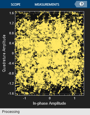
A comparison of the decoded output with the original message stream suggests that the resulting BER is too high for a communication system. The constellation diagram is also shown below:
ber = comm.ErrorRate;
measures = ber(txBits, rxBits);
fprintf('BER = %.2f%%; No. of Bits = %d; No. of errors = %d\n', ...
    measures(1)*100,measures(3), measures(2));
BER = 32.78%; No. of Bits = 30714; No. of errors = 10068
constdiag = comm.ConstellationDiagram('SamplesPerSymbol', 1,...
    'ReferenceConstellation', [], 'ColorFading',true,...
    'Position', gc.constPlotPosition);
% Display received constellation
constdiag(rxSymbs);
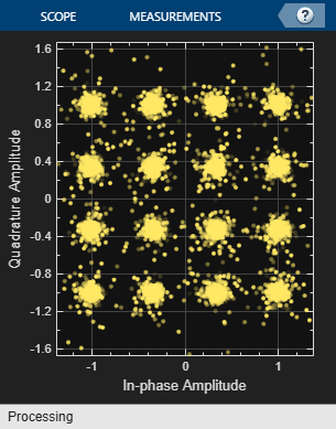
The high BER is mainly due to the mobile being off the steering direction of the base station array. If the mobile is aligned with the steering direction, the BER is greatly improved.
tp.steeringAngle = tp.mobileAngle;

% Steer the transmitter main lobe
wT = steeringvec(gc.fc,[tp.steeringAngle;0]);

[txBits, rxBits,rxSymbs] = helperRerunMIMOBeamformingExample(gc,tp,wT);

reset(ber);
measures = ber(txBits, rxBits);
fprintf('BER = %.2f%%; No. of Bits = %d; No. of errors = %d\n', ...
    measures(1)*100,measures(3), measures(2));
BER = 0.00%; No. of Bits = 30714; No. of errors = 0
constdiag(rxSymbs);
Therefore, the system is very sensitive to the steering error. On the other hand, it is this kind of spatial sensitivity that makes SDMA possible to distinguish multiple users in space.
Phase Shifter Quantization Effect
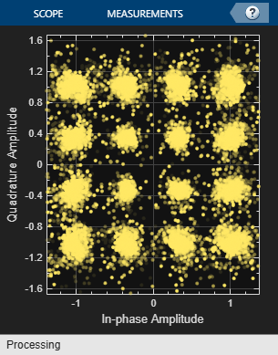
The discussion so far assumes that the beam can be steered toward the exact desired direction. In reality, however, this is often not true, especially when the analog phase shifters are used. Analog phase shifters have only limited precision and are categorized by the number of bits used in phase shifts. For example, a 3-bit phase shifter can only represent 8 different angles within 360 degrees. Thus, if such quantization is included in the simulation, the system performance degrades, which can be observed from the constellation plot.
% analog phase shifter with quantization effect
release(steeringvec);
steeringvec.NumPhaseShifterBits = 4;
wTq = steeringvec(gc.fc,[tp.steeringAngle;0]);

[txBits, rxBits,rxSymbs] = helperRerunMIMOBeamformingExample(gc,tp,wTq);

reset(ber);
measures = ber(txBits, rxBits);
fprintf('BER = %.2f%%; No. of Bits = %d; No. of errors = %d\n', ...
    measures(1)*100,measures(3), measures(2));

constdiag = comm.ConstellationDiagram('SamplesPerSymbol', 1,...
    'ReferenceConstellation', [], 'ColorFading',true,...
    'Position', gc.constPlotPosition);
constdiag(rxSymbs);
BER = 0.02%; No. of Bits = 30714; No. of errors = 5
Summary
This example shows a system level simulation of a point-to-point MIMO-OFDM system employing beamforming. The simulation models many system components such as encoding, transmit beamforming, precoding, multipath fading, channel estimation, equalization, and decoding.
Reference
[1] Houman Zarrinkoub, Understanding LTE with MATLAB, Wiley, 2014
[2] Theodore S. Rappaport et al. Millimeter Wave Wireless Communications, Prentice Hall, 2014
See Also
You can also select a web site from the following list:
Americas
- América Latina (Español)
- Canada (English)
- United States (English)
Europe
- Belgium (English)
- Denmark (English)
- Deutschland (Deutsch)
- España (Español)
- Finland (English)
- France (Français)
- Ireland (English)
- Italia (Italiano)
- Luxembourg (English)
- Netherlands (English)
- Norway (English)
- Österreich (Deutsch)
- Portugal (English)
- Sweden (English)
- Switzerland
- United Kingdom (English)