Delta Sigma Modulator Data Converter with Half-Band Filter for Decimation
This example shows how to use the Delta Sigma Modulator (DSM) data converter building block with a downstream decimation filtering scheme to be used for an Analog-to-Digital converter (ADC) application. DSMs use oversampling technique which results in the phenomenon of noise shaping by which the in-band quantization noise is strongly attenuated. In general, the noise transfer function (NTF) is given by
where N is the order of the DSM and D(z) is the denominator polynomial to be designed. The procedure to systematically design a realizable NTF is explained in [1].
The sampling rate Fs in a DSM is typically much greater than the Nyquist rate. The ratio of Fs to Nyquist rate is called Oversampling Ratio (OSR) given by:
where Fb is the highest frequency content (bandwidth) of the input signal.
DSM output is at the high rate of Fs. Decimation filters are used to reduce the data rate to the Nyquist rate (i.e. 2xFb) and filter the data stream. DSM and the decimation filter together comprise the DSM ADC. This example goes through the case of a DSM using 1-bit quantizer, but it is not uncommon to design DSMs with multi-bit quantizers. In [1], SQNR for a second order single bit modulator is shown empirically to be around 70dB, resulting in an Effective Number Of Bits (ENOB) of 11 bits as explained in the next section. Theoretical SNR calculation of a DSM has been explained in [2].
Design Flow
A typical design flow for modeling a DSM for a specific application is as follows:
1) Design an NTF to achieve a given system specification. The order N depends on the required SQNR and the denominator polynomial D(z) is designed to increase the modulator stability at high frequencies by reducing the gain (low-pass behavior) at high frequencies. (In this example we try to achieve SQNR of 70dB by choosing a 2nd order DSM with OSR = 64. ENOB for this case is close to 11 bits using the expression given below.
2) Choose a DSM structure that provides the best trade-off for the given specifications e.g., quantizer saturation vs. input signal range. A CIFB structure is chosen in this example.
3) Design the decimation filter to be used in conjunction with the DSM to build a DSM ADC. The decimation filter bit-width is chosen to be an integer greater than or equal to ENOB.
4) Run time-domain simulation of the model and check its performance (DSM output spectrum, SNR, etc.)
5) Add impairments to see if specifications are still met or if the architecture needs to be modified. Few key impairments for DSM are finite amplifier gain, thermal noise, etc.
DSM ADC Architecture
DSM ADC comprises a DSM and a decimation filter. Open the model "DSM_Decimation_filter" attached to this example:
model = 'DSM_Decimation_Filter';
open_system(model)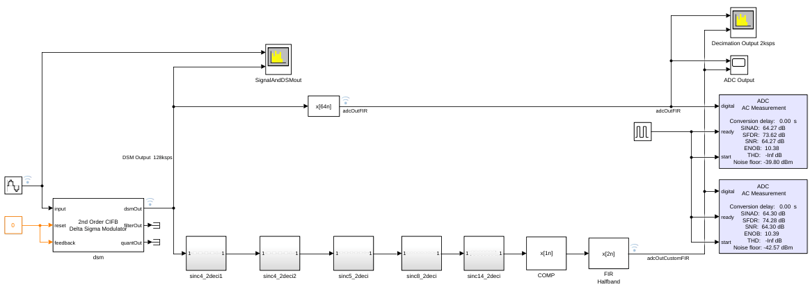
An analog input (sine wave of 990Hz) stimulus is over-sampled by the DSM block and is converted into a digital bit-stream. Specifications for the DSM block are:
Sampling Frequency (Fs) =
128kHzBandwidth (Fb) =
1kHzOver Sampling Ratio (OSR) = 64
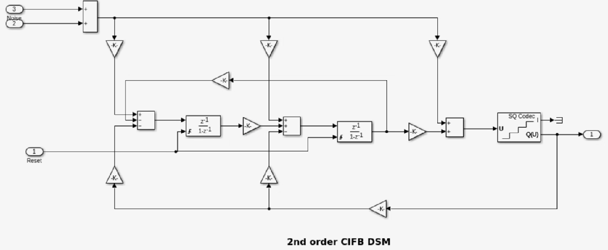
Delta Sigma Modulator
DSM block from the Mixed-Signal Blockset is a masked subsystem containing variant subsystems to define different DSM architectures and orders. Using the block you can select one of the 4 different architectures with orders ranging from 2 to 6. Hence, a total of 20 different architectures can be modeled. DSM architectures can be classified as:
CIFB: Cascade of Integrators, Feedback
CRFB: Cascade of Resonators, Feedback
CIFF: Cascade of Integrators, Feedforward
CRFF: Cascade of Resonators, Feedforward
The coefficients 'a', 'g', 'b' and 'c' for the generalized DSM structures can be determined using the procedure explained in chapter 4 in [1]. The gain coefficients in this example were obtained using the functions provided in the Delta Sigma Toolbox by Richard Schreier [3].
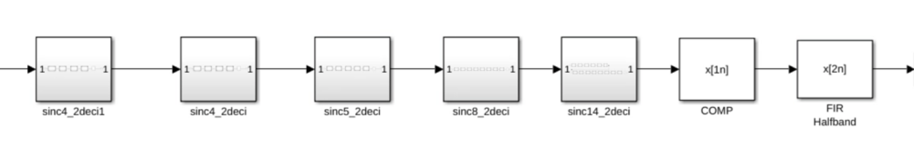
Decimation Filter
A decimation filter serves two purposes: 1) Filter the out-of-band noise 2) "Decimate" the DSM output data rate from Fs to the Nyquist rate 2xFb = (Fs / OSR).
For efficiency of implementation, a decimation filter is implemented as a cascade of digital filters instead of a single stage. In this example, the decimation filter is designed to have an alias attenuation of > 100 dB and < 0.1 dB of passband variation. Since the OSR of DSM is 64, a decimation factor of 64 is implemented. The filter comprises a cascade of 5 sinc filters each with a decimation factor of 2, a compensation FIR filter to compensate for droop in the sinc filters, followed by a half-band filter. The order and gain of the sinc filters are mentioned in Table 14.2 in [1]. See chapter 14 in [1] for a detailed discussion of Decimation Filter design.
Half-band filter is a low pass filter which reduces the maximum bandwidth of sampled data by one octave. In this example, half-band filter has been implemented using FIR Decimation block with the filter coefficients obtained by using the DSP System Toolbox function 'firhalfband' as shown below:
firhalfband('minorder', 0.45, 1E-05);
Alternatively, decimation filter can also be implemented using an FIR Decimation block (from DSP System Toolbox) with the decimation option set to 64 in the mask. More information on FIR Decimation block can be found on the documentation page for dsp.FIRDecimator.
Simulation Results
Simulate the ADC model with 2nd order CIFB DSM block with a sinusoidal signal at 990Hz by running the code below.
sim(model);
DSM output (128Ksps) is fed to a Spectrum analyzer to analyze power spectrum of the ADC output and the spectrum shows a spike at 990Hz as expected. The output data rate is equal to 2ksps since the decimation filter has a decimation factor of 64.
The ADC outputs were fed to "ADC AC measurement" blocks to check the performance of the DSM ADC. SNR and ENOB of the "FIR Decimation" filter are given by
SNR_fir = firFilterOut.SNR
ENOB_fir = firFilterOut.ENOB
SNR and ENOB of the "Cascade of sinc filters" are given by
SNR_sinc = sincFilterOut.SNR
ENOB_sinc = sincFilterOut.ENOB
Now you can add impairments like finite opAmp gain and thermal noise from the "Impairment" tab in the DSM block mask to see their effect on ideal SNR and ENOB numbers.
set_param([model, '/dsm'], 'OLgain', '100'); % Set finite OpAmp gain to 100
set_param([model, '/dsm'], 'EnableNoise', 'On'); % Enable thermal noise impairment
sim(model);
SNR_fir = firFilterOut.SNR
ENOB_fir = firFilterOut.ENOB
SNR_sinc = sincFilterOut.SNR
ENOB_sinc = sincFilterOut.ENOB
References
[1] Shanthi Pavan; Richard Schreier; Gabor C. Temes, Understanding Delta-Sigma Data Converters, second edition, IEEE Press, copyright 2017.
[2] Valeri Mladenov; Panagiotis Karampelas; Georgi Tsenov and Vassiliki Vita, Approximation Formula for Easy Calculation of Signal-to-Noise Ratio of Sigma-Delta Modulators
[3] Richard Schreier (2022). Delta Sigma Toolbox (https://www.mathworks.com/matlabcentral/fileexchange/19-delta-sigma-toolbox), MATLAB Central File Exchange. Retrieved June 14, 2022.
Select a Web Site
Choose a web site to get translated content where available and see local events and offers. Based on your location, we recommend that you select: United States.
You can also select a web site from the following list
Americas
- América Latina (Español)
- Canada (English)
- United States (English)
Europe
- Belgium (English)
- Denmark (English)
- Deutschland (Deutsch)
- España (Español)
- Finland (English)
- France (Français)
- Ireland (English)
- Italia (Italiano)
- Luxembourg (English)
- Netherlands (English)
- Norway (English)
- Österreich (Deutsch)
- Portugal (English)
- Sweden (English)
- Switzerland
- United Kingdom (English)
Asia Pacific
- Australia (English)
- India (English)
- New Zealand (English)
- 中国
- 日本Japanese (日本語)
- 한국Korean (한국어)