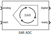
SAR ADC
N-bit successive approximation register (SAR) based ADC
Libraries:
Mixed-Signal Blockset /
ADC /
Architectures
Description
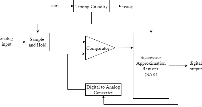
Successive Approximation Register (SAR) based ADC consists of a sample and hold circuit (SHA), a comparator, an internal digital to analog converter (DAC), and a successive approximation register.

When the ADC receives the start command, SHA is placed in hold mode.
The most significant bit (MSB) of the SAR is set to logic 1, and all other
bits are set to logic 0.
The output of the SAR is fed back to a DAC, whose output is compared with the incoming input signal. If the DAC output is greater than the analog input, MSB is reset, otherwise it is left set. The next MSB is now set to 1, and the process is repeated until every bit the SAR is compared. The final value of the SAR at the end of this process corresponds to the analog input value. The end of the conversion process is indicated by the ready signal.
Ports
Input
Analog input signal, specified as a scalar.
Data Types: double
External clock to start conversion, specified as a scalar. The analog to digital conversion process starts at the rising edge of the signal at the start port.
Data Types: double
Output
Converted digital output signal, returned as a scalar.
Data Types: fixed point | single | double | int8 | int16 | int32 | uint8 | uint16 | uint32 | Boolean
Determines whether the analog to digital conversion is complete, returned as a scalar.
Data Types: double
Parameters
Configuration
Number of physical output bits, specified as a unitless positive real integer in
the range [1, 26]. Number of bits determines
the resolution of the ADC.
Programmatic Use
Use
get_param(gcb,'NBits')to view the current Number of bits.Use
set_param(gcb,'NBits',value)to set Number of bits to a specific value.
Data Types: double
ADC dynamic range, specified as a 2-element row vector in volts.
Programmatic Use
Block parameter:
InputRange |
| Type: character vector |
| Values: 2-element row vector |
Default:
[-1 1] |
Data Types: double
Select to connect to an external start conversion clock. By default, this option is selected. If you deselect this option, a Sampling Clock Source block inside the SAR ADC is used to generate the start conversion clock.
Frequency of internal start conversion clock, specified as a positive real scalar in Hz. Conversion start frequency determines the rate of the ADC.
Dependencies
This parameter is only available when Use external start clock is not selected.
Programmatic Use
Use
get_param(gcb,'StartFreq')to view the current value of Conversion start frequency (Hz).Use
set_param(gcb,'StartFreq',value)to set Conversion start frequency (Hz) to a specific value.
Data Types: double
RMS aperture jitter added as an impairment to the start conversion clock, specified as a real nonnegative scalar in s. Set RMS aperture jitter value to zero if you want a clean clock signal.
Dependencies
This parameter is only available when Use external start clock is not selected.
Programmatic Use
Use
get_param(gcb,'StartClkJitter')to view the current value of RMS aperture jitter (s).Use
set_param(gcb,'StartClkJitter',value)to set RMS aperture jitter (s) to a specific value.
Data Types: double
Frequency of the SAR clock, specified as a real scalar in Hz. SAR Frequency (Hz) must be high enough to allow the ADC to perform Nbits comparison, where Nbits is the Number of bits of the ADC. The block has one cycle overhead due to algebraic loop removal. So, the clock must run for one additional cycle before the output is ready. So, the SAR Frequency (Hz) (fSAR) is given by the equation , where fstart is the Conversion start frequency.
Programmatic Use
Use
get_param(gcb,'SARFreq')to view the current value of SAR Frequency (Hz).Use
set_param(gcb,'SARFreq',value)to set SAR Frequency (Hz) to a specific value.
Inherit the output polarity and data type from the analog input signal to the ADC. If you select this option, the ADC ignores the Output polarity and Output data type parameters. The ADC output has the same polarity as the input and the data type is double.
Defines the ADC output data polarity.
If Output polarity is set to Auto, the
minimum and maximum values of the output are determined by the polarity of the
Input range.
If Output polarity is set to Bipolar,
the outputs are between -2Nbits-1 and
2Nbits-1-1.
If Output polarity is set to Unipolar,
the outputs are between 0 and
2Nbits-1.
Dependencies
To enable this parameter, deselect the Match input scale option.
Programmatic Use
Block parameter:
OutputPolarity |
| Type: character vector |
Values:
Auto | Bipolar |
Unipolar |
Default:
Auto |
Defines ADC output data type.
Unsigned integers and fixed-point types (fixdt(0,Nbits))
are not available when the Output polarity is set to
Bipolar or Auto.
Signed integers and fixed-point types (fixdt(1,Nbits)) are
not available when the Output polarity is set to
Unipolar.
Dependencies
To enable this parameter, deselect the Match input scale option.
Programmatic Use
Block parameter:
OutDataType |
| Type: character vector |
Values:
double | single |
int8 | int16 |
int32 | uint8 |
uint16 | uint32 |
fixdt(0,Nbits) |
fixdt(1,Nbits) | Inherit: Inherit
via back propagation |
Default:
fixdt(1,Nbits) |
Impairments
Select to enable linearity impairments such as offset error and gain error in ADC simulation. By default, this option is deselected.
Shifts quantization steps by specific value, specified as a scalar in least significant bit (LSB) or %.
Note
The full scale range of the converter is defined as the difference between the last and first code on the +0.5 LSB compensated transfer curve. In a +0.5 LSB compensated transfer curve, first code is 0.5 LSB wide while the last code is 1.5 LSB wide. The input values must be considered within the full scale range of the converter.
Note
LSB is calculated by the equation .
Dependencies
This parameter is only available when Enable Linearity Impairments is selected.
Programmatic Use
Use
get_param(gcb,'OffsetError')to view the current value of Offset error (LSB).Use
set_param(gcb,'OffsetError',value)to set Offset error (LSB) to a specific value.
Data Types: double
Error on the slope of the straight line interpolating ADC transfer curve, specified as a real scalar in %FS, FS, or LSB.
Note
The full scale range of the converter is defined as the difference between the last and first code on the +0.5 LSB compensated transfer curve. In a +0.5 LSB compensated transfer curve, first code is 0.5 LSB wide while the last code is 1.5 LSB wide. The input values must be considered within the full scale range of the converter.
Note
LSB is calculated by the equation .
Dependencies
To enable this parameter, select Enable Linearity Impairments in the Impairments tab.
Programmatic Use
Block parameter:
GainError |
| Type: character vector |
| Values: real scalar |
Default:
2 LSB |
Data Types: double
Version History
Introduced in R2019a
MATLAB Command
You clicked a link that corresponds to this MATLAB command:
Run the command by entering it in the MATLAB Command Window. Web browsers do not support MATLAB commands.
Select a Web Site
Choose a web site to get translated content where available and see local events and offers. Based on your location, we recommend that you select: .
You can also select a web site from the following list
How to Get Best Site Performance
Select the China site (in Chinese or English) for best site performance. Other MathWorks country sites are not optimized for visits from your location.
Americas
- América Latina (Español)
- Canada (English)
- United States (English)
Europe
- Belgium (English)
- Denmark (English)
- Deutschland (Deutsch)
- España (Español)
- Finland (English)
- France (Français)
- Ireland (English)
- Italia (Italiano)
- Luxembourg (English)
- Netherlands (English)
- Norway (English)
- Österreich (Deutsch)
- Portugal (English)
- Sweden (English)
- Switzerland
- United Kingdom (English)
