Validate System
This section explains how to evaluate the accuracy of the plant (motor and inverter) model of the physical motor and load connected to the motor. Validate the plant model and verify that the results are close to the physical system measurements before using the plant model for implementing advanced algorithms. You can validate the system by comparing the step response of speed control and current control during simulation and after deployment to the target hardware connected to the motor.
Use the example Tune Control Parameter Gains in Hardware and Validate Plant to measure the step response of the current and speed controllers. The host model in this example communicates the current reference to the target hardware and measures the step response of the current controller.
You can use any speed control example from Motor Control Blockset™ to validate the system.
Validate speed control by comparing the step response during simulation with the hardware test values.
Validate the d-axis current control by electrically or mechanically locking the rotor and comparing the step response during simulation with the hardware test results.
You can use another method to validate the d-axis current control. Run the motor at a constant speed and provide a step change in the reference d-axis current. This requires two modifications in the speed control subsystem of the target model. Set a constant speed reference input. Command Id reference from the host model. Compare the step response of the d-axis current during simulation with the response obtained during the hardware tests.
Validate the q-axis current control by mechanically coupling the motor with an external dynamo-meter running in speed control. This requires two modifications in the speed control subsystem of the target model. Discard the Id and Iq reference from the speed PI controller output. Command Id reference from the host model. Compare the step response of the q-axis current during simulation with the response obtained during the hardware tests.
Warning
When capturing the step response in d-axis current control, always use a positive step. Negative values of Id can damage the permanent magnet in the PMSM.

See the example Tune Control Parameter Gains in Hardware and Validate Plant to deploy the model to the hardware. Perform motor parameter estimation because an accurate plant model is important to ensure that the simulation results match the hardware test results.
Calculate Physical Motor Load in Target Hardware
Before comparing the controller responses during simulation with the responses obtained after target hardware deployment, the load torque in plant simulation must match the motor load in the physical system. Follow these steps to calculate the load torque in the physical system and update the calculated load torque in the plant model.
Run the host model to connect it to the target hardware through serial communication.
Set Select Motor operating mode to Speed control.
The motor spins in speed control.
Select Id_meas in Monitor Signal #1 and Iq_meas in Monitor signal #2. Read the
Id_measandIq_measvalues from the scope.Convert the per-unit (PU) current to Amperes by multiplying it with
PU_System.I_base.Calculate the load torque in Nm using this equation:
where,
= Permanent magnet flux linkage (pmsm.Flux_PM)
= Inductance in Henry (pmsm.Ld, pmsm.Lq)
= Current measured in Amperes
Id_meas, the measured Id current (in PU), equals0.In the
mcb_pmsm_operating_mode_f28379d/Motor and Inverter/Plant
                            Model (sim)
sub system, provide the calculated load torque value as an input to the LdTrq port of the PMSM motor block.
Compare Speed Controller Response During Simulation with Target Hardware Results
During simulation, provide a speed step input and note the speed response. On the target hardware, command the speed reference step input and observe the speed feedback. Compare the resulting step response during simulation with the response obtained from target hardware to determine the accuracy of the plant model.
Simulate the model
mcb_pmsm_operating_mode_f28379d. Plot the reference speed and the measured speed signals. By default, this example provides a step input of0.2to0.5to the simulation model.Run the host model to communicate with the target hardware.
Change Select Motor operating mode from Stop to Speed control.
In the host model, select Speed_ref in Monitor Signal#1 and Speed_meas in Monitor Signal#2.
Open the scope in the host model.
In host model interface, change the
speed_reffrom0.2to0.5and observe the step change in the scope.Compare the step response obtained from the hardware with the simulation results.
Step Response Analysis for Speed Controller
Compare the step response obtained from simulation with the measurements obtained from the target hardware. The results may vary depending on the tolerances in the plant model. Generally, simulation results are close to the values measured on the target hardware.
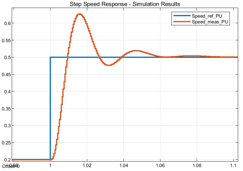

| Peak overshoot (%) | Peak time (ms) | Rise time (ms) | Settling time (ms) | |
|---|---|---|---|---|
| Simulation results | 20.13% | 16.023 | 5.561 | 61.027 |
| Hardware results | 22 % | 14.324 | 5.041 | 51.148 |
Compare Current Controller Response During Simulation with Target Hardware Results
During simulation, provide a step current reference and note the current response. This example needs some changes to simulate the current reference step input. Follow these steps to perform the model changes. When using the target hardware, command the current reference step input and observe the current feedback. Compare the resulting step response in simulation with the response obtained from the target hardware to determine the accuracy of the plant model.
For hardware measurements, run the host model.
Change Select Motor operating mode from Stop to Torque control.
Select Id_ref in Monitor Signal#1 and Id_meas in Monitor Signal#2 in the host model.
Open the scope in the host model.
Change
Id_reffrom0.02to0.22and observe the step change in the scope. Ensure that the motor is not running. The scope displays the step response for theId_refinput.For simulation, make these two changes in the model. In the
mcb_pmsm_operating_mode_f28379d/TorqueControl/Control
                            Modes/torque_control
subsystem add a step input for the d-axis current controller. Choose a step input of0.02to0.22at1second. Select time sample as-1. In the data-type conversion block, select the output datatype asfixdt(1,32,17).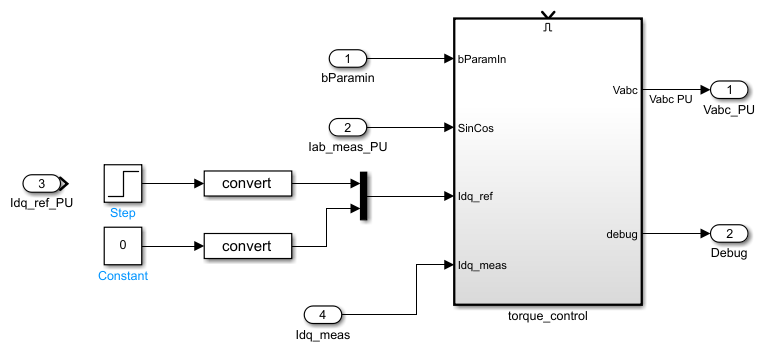
In the PMSM motor block available in the
mcb_pmsm_operating_mode_f28379d/Motor and Inverter/Plant Model
                            (sim)
subsystem, change the Mechanical input configuration to Speed and input0to the Spd input port.Run the simulation and measure the
Idref_PUandIdmeas_PUvalues in the Simulation Data Inspector.Compare the step response obtained from the hardware with the simulation results.
Step Response Analysis for d-axis Current Controller
Compare the scope results obtained from simulation with the measurements from the target hardware. The results may vary depending on the tolerances in the plant model. With an accurate plant model, the simulation results are closer to the measured results from the target hardware.

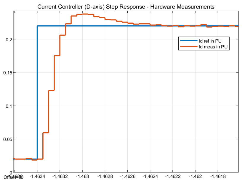
| Peak overshoot (%) | Peak time (µs) | Rise time (µs) | Settling time (µs) | |
|---|---|---|---|---|
| Simulation results | 14 % | 300 | 150 | 500 |
| Hardware results | 8.18 % | 400 | 150 | 800 |
The accuracy of the plant model improves the accuracy of simulation, and therefore, it helps match the simulation results to the hardware test results.
Tip
If the simulation results differ considerably from the hardware measurements, verify the delay and scaling factor in the plant model.
Note
For the q-axis current controller, align the motor to the d-axis and mechanically lock the rotor. Follow this for the d-axis current controller for comparative analysis. You can achieve external mechanical locking through the mechanical braking system or by coupling with a dynamo-meter motor running in speed control.