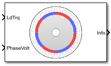
Surface Mount PMSM
Three-phase exterior permanent magnet synchronous motor with sinusoidal back electromotive force
Libraries:
Powertrain Blockset /
Propulsion /
Electric Motors and Inverters
Motor Control Blockset /
Electrical Systems /
Motors
Description
The Surface Mount PMSM block implements a three-phase exterior permanent magnet synchronous motor (PMSM) with sinusoidal back electromotive force. The block uses the three-phase input voltages to regulate the individual phase currents, allowing control of the motor torque or speed.
By default, the block sets the Simulation
type parameter to Continuous to use a
continuous sample time during simulation. If you want to generate code for fixed-step
double- and single-precision targets, considering setting the parameter to
Discrete. Then specify a Sample Time,
Ts parameter.
On the Parameters tab, if you select
Back-emf constant (Ke) or Torque constant
(Kt), the block implements one of these equations to calculate the permanent
flux linkage constant.
| Setting | Equation |
|---|---|
Back-emf constant (Ke) |
|
Torque constant (Kt) |
|
Motor Construction
This figure shows the motor construction with a single pole pair on the rotor.
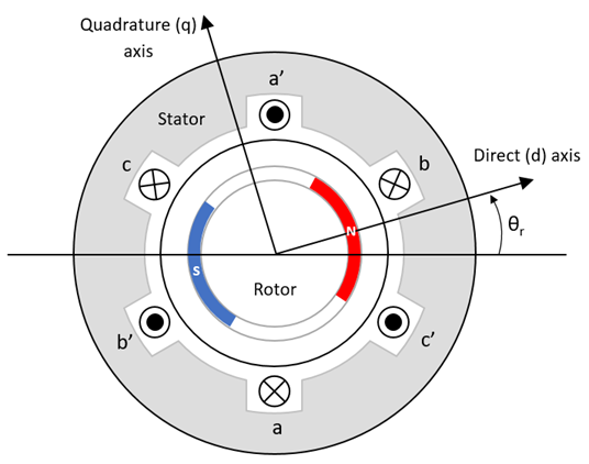
The motor magnetic field due to the permanent magnets creates a sinusoidal rate of change of flux with motor angle.
For the axes convention, the a-phase and permanent magnet fluxes are aligned when motor angle θr is zero.
Three-Phase Sinusoidal Model Electrical System
The block implements these equations, expressed in the motor flux reference frame (dq frame). All quantities in the motor reference frame are referred to the stator.
The Lq and Ld inductances represent the relation between the phase inductance and the motor position due to the saliency of the motor magnets. For the surface mount PMSM, .
The equations use these variables.
Lq, Ld | q- and d-axis inductances (H) |
R | Resistance of the stator windings (ohm) |
iq, id | q- and d-axis currents (A) |
vq, vd | q- and d-axis voltages (V) |
ωm | Angular mechanical velocity of the motor (rad/s) |
ωe | Angular electrical velocity of the motor (rad/s) |
λpm | Permanent magnet flux linkage (Wb) |
| Ke | Back electromotive force (EMF) (Vpk_LL/krpm, where Vpk_LL is the peak voltage line-to-line measurement) |
Kt | Torque constant (N·m/A) Kt = Rated torque of motor / Ia_peak_rated, where Ia_peak_rated is the peak amplitude of phase-a at rated current operation. |
P | Number of pole pairs |
Te | Electromagnetic torque (Nm) |
Θe | Electrical angle (rad) |
Mechanical System
The motor angular velocity is given by:
The equations use these variables.
J | Combined inertia of motor and load (kgm^2) |
F | Combined viscous friction of motor and load (N·m/(rad/s)) |
θm | Motor mechanical angular position (rad) |
Tm | Motor shaft torque (Nm) |
Te | Electromagnetic torque (Nm) |
Tf | Motor shaft static friction torque (Nm) |
ωm | Angular mechanical velocity of the motor (rad/s) |
Power Accounting
For the power accounting, the block implements these equations.
| Bus Signal | Description | Variable | Equations | ||
|---|---|---|---|---|---|
|
|
| Mechanical power | Pmot | |
PwrBus | Electrical power | Pbus | |||
|
| PwrElecLoss | Resistive power loss | Pelec | ||
PwrMechLoss | Mechanical power loss | Pmech | When Mechanical input
configuration is set to
When Mechanical
input configuration is set to
| ||
|
| PwrMtrStored | Stored motor power | Pstr | ||
The equations use these variables.
Rs | Stator resistance (ohm) |
ia, ib, ic | Stator phase a, b, and c current (A) |
isq, isd | Stator q- and d-axis currents (A) |
van, vbn, vcn | Stator phase a, b, and c voltage (V) |
ωm | Angular mechanical velocity of the motor (rad/s) |
F | Combined motor and load viscous damping N·m/(rad/s) |
Te | Electromagnetic torque (Nm) |
Tf | Combined motor and load friction torque (Nm) |
Amplitude Invariant dq Transformation
The block uses these equations to implement amplitude invariant dq transformation to ensure that the dq and three phase amplitudes are equal.
The equations use these variables.
Θda | dq stator electrical angle with respect to the rotor a-axis (rad) |
vsq, vsd | Stator q- and d-axis voltages (V) |
isq, isd | Stator q- and d-axis currents (A) |
| va, vb, vc | Stator voltage phases a, b, c (V) |
| ia, ib, ic | Stator currents phases a, b, c (A) |
Ports
Input
Output
Parameters
Tips
If you want to provide motor parameters through an input port instead of specifying them as block parameters, use the PMSM HDL block.
References
[1] Kundur, P. Power System Stability and Control. New York, NY: McGraw Hill, 1993.
[2] Anderson, P. M. Analysis of Faulted Power Systems. Hoboken, NJ: Wiley-IEEE Press, 1995.
Extended Capabilities
Version History
Introduced in R2017a