Main Content

PFC Current Controller

R2026b

Regulate inductor current in a power factor correction boost converter

Since R2026b

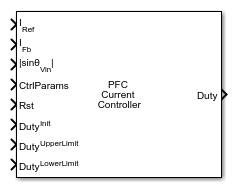
  • PFC Current Controller block icon.

Libraries:
Power Converter Control with Motor Control Blockset / Control / Power Factor Correction

Description

The PFC Current Controller block implements a discrete-time PI controller for the inner current loop of a power factor correction (PFC) boost converter. The block computes a PWM duty cycle by comparing a sinusoidal current reference to the measured inductor current, using PI gains supplied through the CtrlParams input bus from a PFC Controller Gains block.

The block computes the current error as the difference between the reference at IRef and the measured inductor current at IFb, and applies the PI controller to produce a duty cycle command at Duty. To enable unity power factor operation, connect the |sinθVin| input to the absolute value of the normalized grid voltage sine wave. In a cascaded PFC structure, derive IRef by multiplying the IOut output of a PFC Voltage Controller block by |sinθVin|.

The block supports bumpless transfer through the Rst and DutyInit ports. When Rst is nonzero, the block sets the duty cycle output to the value at DutyInit and preloads the integrator state so the output resumes from that duty cycle when you release the reset. Use DutyUpperLimit and DutyLowerLimit to clamp the duty cycle and protect the converter from excessive switch stress.

To use this block, connect the CtrlParams output of a PFC Controller Gains block configured for the same converter specifications. Connect the sinusoidal current reference to IRef, the measured inductor current to IFb, and the normalized grid sine to |sinθVin|. Connect the Duty output to the duty cycle input of a PWM generation block in your converter model.

Examples
Ports

Input

expand all

Desired inductor current setpoint in amperes, specified as a scalar. In a typical PFC application, compute this by multiplying the output of the PFC Voltage Controller by the normalized grid voltage shape (|sinθVin|), so that the inductor current tracks a sinusoid in phase with the grid voltage.

Data Types: double | single

Measured boost inductor current in amperes, specified as a scalar. Connect this port to a current sensor output in your model. The controller subtracts this value from IRef to compute the current error.

Data Types: double | single

Absolute value of the normalized AC grid voltage sine wave, in the range [0, 1], specified as a scalar. Multiplying the current demand from the voltage loop by this signal produces a sinusoidal current reference for unity power factor operation. Obtain this signal from a PLL block tracking the grid phase angle.

Data Types: double | single

Controller gain parameters bus containing the discrete-time current controller PI gains, specified as a bus. Connect the CtrlParams output of a PFC Controller Gains block.

Data Types: bus

Boolean signal that resets the integrator state when asserted (nonzero), specified as a scalar. When reset occurs, the output is set to the value at DutyInit.

Data Types: double | single

Initial output duty cycle applied when Rst is asserted, specified as a scalar in the range [0, 1]. This value preloads the integrator for bumpless transfer after a reset event.

Data Types: double | single

Maximum allowed duty cycle, specified as a scalar in the range [0, 1]. The block clamps the output to this value when the computed duty cycle exceeds it.

Data Types: double | single

Minimum allowed duty cycle, specified as a scalar in the range [0, 1]. The block clamps the output to this value when the computed duty cycle falls below it.

Data Types: double | single

Output

expand all

Duty cycle command in the range [DutyLowerLimit, DutyUpperLimit], returned as a scalar. Connect this signal to the duty cycle input of a PWM generation block to drive the PFC boost converter switch.

Data Types: double | single

Parameters

expand all

To edit block parameters interactively, use the Property Inspector. From the Simulink® Toolstrip, on the Simulation tab, in the Prepare gallery, select Property Inspector.

Specifies how the block limits the integrator when the output duty cycle reaches DutyUpperLimit or DutyLowerLimit.

Select Clamping (default) to stop integration when the output is at a limit and the integrator input has the same sign as the accumulated value. This method prevents further windup without requiring an additional coefficient.

Select None to disable anti-windup. The integrator continues to accumulate during saturation.

Select Back-calculation to feed back the difference between the unsaturated and saturated output to the integrator input, scaled by the Back-Calculation Coefficient (Kb). This method unwinds the integrator while the output is saturated.

Programmatic Use

To set the block parameter value programmatically, use the set_param function.

Parameter: antiwindup
Values: "Clamping" (default) | "None" | "Back-calculation"

Example: set_param(gcb,"antiwindup","Back-calculation")

Gain for the back-calculation anti-windup loop, specified as a positive scalar. The block uses this value to scale the feedback correction applied to the integrator state when the output saturates. Larger values cause the integrator to unwind faster after saturation. A typical starting value is 1. Increase it if you observe slow recovery after transient events that cause output saturation.

Dependencies

This parameter is visible when Anti-Windup Method is set to Back-calculation.

Programmatic Use

To set the block parameter value programmatically, use the set_param function.

Parameter: calcoefficient
Values: "1" (default) | positive scalar in quotes
Data Types: char | string

Example: set_param(gcb,"calcoefficient","2")

Extended Capabilities

expand all

C/C++ Code Generation
Generate C and C++ code using Simulink® Coder™.

Version History

Introduced in R2026b