Sensorless Field-Oriented Control of PMSM Using DC Shunt Current Sensing
This example shows how to implement sensorless field-oriented control (FOC) using only a single DC bus-based current measurement to run a permanent magnet synchronous motor (PMSM).
The Field-Oriented Control algorithm needs precise position and three-phase current feedback to follow a motor reference speed accurately. Accurate current sensing helps minimize torque ripple, and therefore, enhances dynamic performance of the motor with minimum audible noise.
You can measure the three-phase currents of a motor using the following three methods:
Inline current sensing
Inverter leg current sensing
DC bus (single shunt) current sensing
The following image shows the current sensing regions in an inverter circuit for each of these methods.

The example uses the sensorless Extended EMF Observer block to estimate the motor position. Instead of using inline current sensing or inverter leg sensing, this example utilizes DC bus (single shunt) current sensing to determine the three-phase motor currents.
The example uses only one shunt resistance for measuring motor currents (instead of two or three resistances used by the other techniques). Therefore, it uses only a single analog to digital converter (ADC) for current measurement, and thereby, reduces production costs effectively by reducing the number of hardware peripherals.
DC Bus Current Sensing and Phase Shifting
The example uses the Phase Current Extractor for Single Shunt FOC block to extract the phase currents from DC shunt current. The example also uses the PWM Phase Shift for Single Shunt FOC block to add the required phase shift in three-phase PWM pulses.
The FOC current controller uses the computed rotor position as well as measured motor currents to compute the three-phase voltages required for the motor to follow a given reference speed. The controller converts these three-phase voltages into pulse width modulation (PWM) duty cycles that operate the six inverter switches.
To generate PWM duty cycles, the current controller in the example model uses a 20 kHz triangular carrier waveform (with sampling time of 50 microseconds) and generates three pulse trains that operate the inverter switches.
The current measurement algorithm shifts the PWM pulses. Using this compensation, the example algorithm can determine two phase currents using which it eventually determines the third phase current mathematically.
Model
This example includes the PMSMFocSensorlessDCShuntCurrentSenseF28069m Simulink® model.
You can use this model for both simulation and code generation.

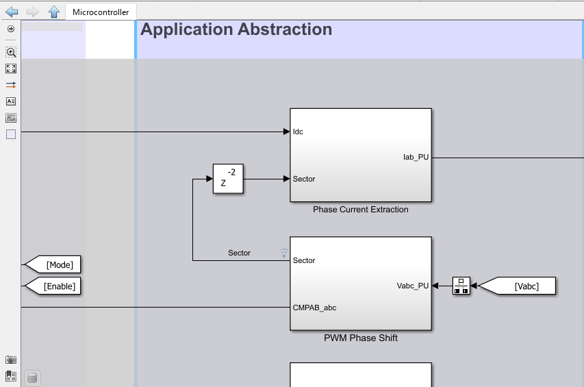
The Application Abstraction layer in the model includes the two blocks for obtaining phase currents and adding the phase shift.
Required MathWorks Products
To simulate model:
Motor Control Blockset™
Simscape™ Electrical™
To generate code and deploy model:
Motor Control Blockset
Embedded Coder®
C2000™ Microcontroller Blockset
Prerequisites
1. Obtain the motor parameters. The Simulink model uses default motor parameters that you can replace with the values from either the motor datasheet or other sources.
However, if you have the motor control hardware, you can estimate the parameters for the motor that you want to use, by using the Motor Control Blockset parameter estimation tool. For instructions, see Estimate Motor Parameters Using Motor Control Blockset Parameter Estimation Tool.
The parameter estimation tool updates the motorParam variable (in the MATLAB® workspace) with the estimated motor parameters.
2. If you obtain the motor parameters from the datasheet or other sources, update the motor parameters and inverter parameters in the model initialization script PMSMFocSensorlessDCShuntCurrentSenseF28069mData associated with the Simulink models. For instructions, see Estimate Control Gains and Tune Control Parameters.
If you use the parameter estimation tool, you can update the inverter parameters, but do not update the motor parameters in the model initialization script. The script automatically extracts motor parameters from the updated motorParam workspace variable.
Simulate Model
This example supports simulation. Follow these steps to simulate the model.
1. Open a target model included with this example.
2. To simulate the model, click Run on the Simulation tab.
3. To view and analyze the simulation results, click Data Inspector on the Simulation tab.
Generate Code and Deploy Model to Target Hardware
This section instructs you on how to generate code and run the sensorless extended EMF observer based FOC algorithm on the target hardware.
This example uses a host and a target model. The host model is a user interface to the controller hardware board. You can run the host model on the host computer. The prerequisite to use the host model is to deploy the target model to the controller hardware board. The host model uses serial communication to command the target Simulink model and run the motor in closed-loop control.
Required Hardware
This example supports the following hardware configuration.
F28069M controller card + DRV8312-69M-KIT inverter:
PMSMFocSensorlessDCShuntCurrentSenseF28069m
For connections related to the preceding hardware configuration, see F28069 control card configuration.
Generate Code and Run Model on Target Hardware
1. Simulate the target model and observe the simulation results.
2. Complete the hardware connections.
3. The model automatically computes the ADC or current offset value. To disable this functionality (enabled by default), update the value 0 to the variable inverter.ADCOffsetCalibEnable in the model initialization script.
4. Open the target model for the hardware configuration that you want to use. If you want to change the default hardware configuration settings for the model, see Model Configuration Parameters.
5. Click Build, Deploy & Start on the Hardware tab to deploy the target model to the hardware.
6. In the target model, click the mcb_host_model_f28069m.slx host model hyperlink to open the associated host model.
For more information on serial communication between the host and target models, see Host-Target Communication.
7. In the model initialization script PMSMFocSensorlessDCShuntCurrentSenseF28069mData associated with the target model, specify the communication port using the variable target.comport. The example uses this variable to update the Port parameter of the Host Serial Setup, Host Serial Receive, and Host Serial Transmit blocks available in the host model.
8. Update the Reference Speed value in the host model.
Note
* Before you run the motor at the required Reference Speed, start running the motor at 0.1 x pmsm.N_base speed by using open-loop control. Then transition to closed-loop control by increasing the speed to 0.25 x pmsm.N_base (where, pmsm.N_base is the MATLAB workspace variable for the base speed of the motor).
* High acceleration and deceleration may affect the sensorless position computation.
9. Click Run on the Simulation tab to run the host model.
10. Change the position of the Motor switch to On, to start running the motor in the open-loop condition (by default, the motor spins at 10% of base speed).
Note: Do not run the motor (using this example) in the open-loop condition for a long time. The motor may draw high currents and produce excessive heat.
The open-loop control algorithm used in this example runs the motor with Reference Speed that is less than or equal to 10% of the base speed.
When you run this example on the hardware at low Reference Speed, due to a known issue, the PMSM may not follow the low Reference Speed.
11. Increase the motor Reference Speed beyond 10% of the base speed to switch from open-loop to closed-loop control.
Note: To change the direction of rotation of the motor, reduce the motor Reference Speed to a value less than 10% of the base speed. This brings the motor back to the open-loop condition. Change the direction of rotation by providing a negative Reference Speed (keeping the Reference Speed magnitude identical). Then, transition to the closed-loop condition.
12. Observe the debug signals from the Serial Communication subsystem in the scope available in the host model.