LTE Uplink EVM and In-Band Emissions Measurements
This example shows how the LTE Toolbox™ can be used to perform Error Vector Magnitude (EVM) and in-band emissions measurements on an uplink signal as per TS 36.101 Annex F [ 1 ].
Introduction
TS 36.101 Annex F [ 1 ] defines two measurements for an uplink transmission, EVM and in-band emissions:
EVM is used as a measure of the received signal constellation error. EVM is defined as the difference between the ideal received waveform and the measured waveform for allocated resource blocks. The average EVM is measured at two locations in time (low and high), where the low and high locations correspond to the alignment of the FFT window within the start and end of the cyclic prefix. LTE Toolbox requires the low and high locations to be specified as a fraction of the cyclic prefix length.
A User Equipment (UE) transmission is created using a Reference Measurement Channel (RMC) and random Physical Uplink Shared Channel (PUSCH) data and impaired by introducing additive noise to model transmitter EVM, and frequency and IQ offsets. The transmitted waveform is synchronized before the function computing EVM and in-band emissions.
Transmitter
To generate the RMC the function lteRMCUL creates a configuration structure for given UE settings specific to a given Fixed Reference Channel (FRC). This structure is used by lteRMCULTool to generate a UE transmission with random PUSCH data.
% Set the seeds of random number generators used to 0
rng(0);

% UE Configuration, TS36.101 FRC
frc = lteRMCUL('A3-1');
frc.PUSCH.RVSeq = 0;    % Redundancy version
frc.TotSubframes = 15;  % Total number of subframes to generate

% Create UE transmission with random PUSCH data
txWaveform = lteRMCULTool(frc,randi([0 1], frc.PUSCH.TrBlkSizes(1), 1));
Impairment Modeling
Impairments are added to the transmission to simulate a device under test:
1.2% transmit EVM modeled with additive noise.
33 Hz frequency offset.
0.01 - 0.005j IQ offset
% Model EVM with additive noise
scfdmaInfo = lteSCFDMAInfo(frc);
txEVMpc = 1.2; % Desired transmit EVM in percent
evmModel = txEVMpc/(100*sqrt(double(scfdmaInfo.Nfft)))* ...
    complex(randn(size(txWaveform)),randn(size(txWaveform)))/sqrt(2);
rxWaveform = txWaveform+evmModel;

% Add frequency offset impairment to received waveform
foffset = 33.0;         % Frequency offset in Hertz
t = (0:length(rxWaveform)-1).'/scfdmaInfo.SamplingRate;
rxWaveform = rxWaveform.* exp(1i*2*pi*foffset*t);

% Add IQ offset
iqoffset = complex(0.01, -0.005);
rxWaveform = rxWaveform+iqoffset;
Receiver
The received waveform is synchronized to allow for the measurements to be performed
% Apply frequency estimation and correction for the purposes of performing
% timing synchronization
foffset_est = lteFrequencyOffset(frc, rxWaveform);
rxWaveformFreqCorrected = ...
    lteFrequencyCorrect(frc, rxWaveform, foffset_est);

% Synchronize to received waveform
offset = lteULFrameOffset(frc, frc.PUSCH, rxWaveformFreqCorrected);
rxWaveform  = rxWaveform(1+offset:end,:);
Perform Measurements
The PUSCH EVM, PUSCH DRS EVM and in-band emissions are calculated by calling hPUSCHEVM.
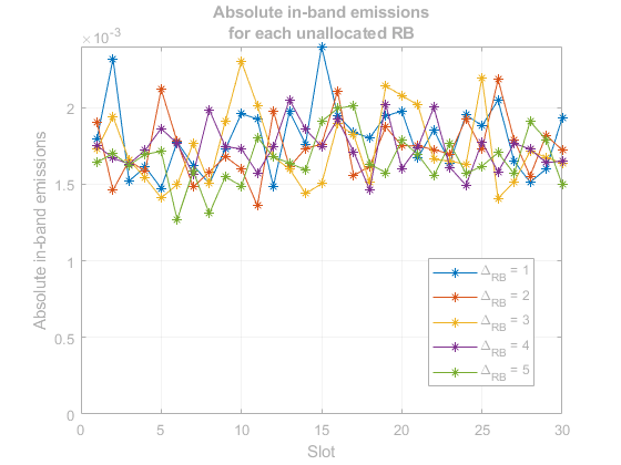
The EVM results and absolute in-band emissions for each  and slot number are displayed. is the starting frequency offset between the allocated resource block (RB) and the measured non-allocated RB, i.e.
  for the first adjacent RB outside of the allocated bandwidth. A number of plots are also produced:
EVM versus OFDM symbol
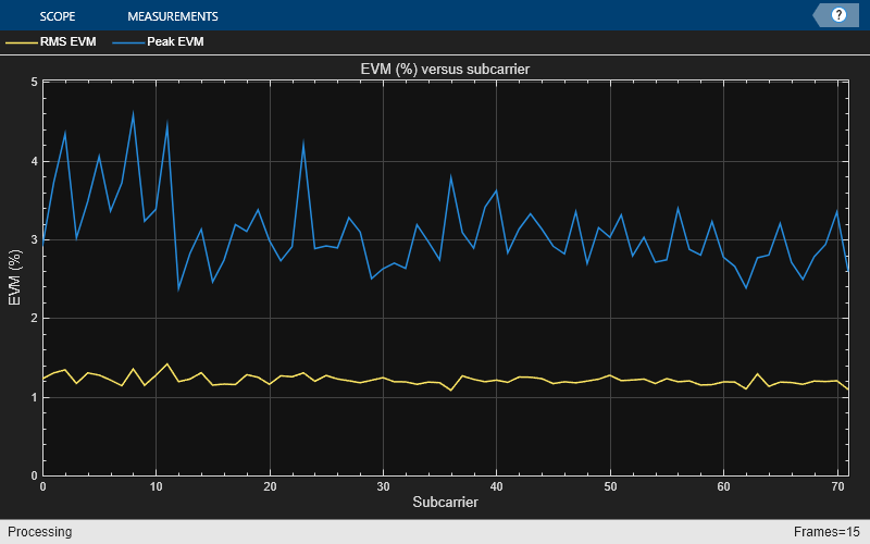
EVM versus subcarrier
EVM versus resource block
EVM versus OFDM symbol and subcarrier (i.e. the EVM resource grid)
Note that the EVM measurement displayed at the command window is only calculated across allocated PUSCH resource blocks, in accordance with the LTE standard. The EVM plots are shown across all resource blocks (allocated or unallocated), allowing the in-band emissions to be viewed. In unallocated resource blocks, the EVM is calculated assuming that the received resource elements have an expected value of zero.
The EVM of each E-UTRA carrier for QPSK/BPSK, 16QAM, 64QAM and 256QAM modulation should not exceed the EVM level of 17.5%, 12.5%, 8% and 3.5% respectively as per TS 36.101 Table 6.5.2.1.1-1 [ 1 ].
% Compute EVM and in-band emissions
[evmpusch, evmdrs, emissions, plots] = hPUSCHEVM(frc, rxWaveform);

% Plot the absolute in-band emissions
if (~isempty(emissions.DeltaRB))
    hPUSCHEVMEmissionsPlot(emissions);
end
Low edge PUSCH EVM, slot 0: 1.231%
Low edge PUSCH EVM, slot 1: 1.231%
Low edge DRS EVM, slot 0: 1.298%
Low edge DRS EVM, slot 1: 1.266%
High edge PUSCH EVM, slot 0: 1.176%
High edge PUSCH EVM, slot 1: 1.240%
High edge DRS EVM, slot 0: 1.226%
High edge DRS EVM, slot 1: 1.330%
Low edge PUSCH EVM, slot 2: 1.156%
Low edge PUSCH EVM, slot 3: 1.260%
Low edge DRS EVM, slot 2: 1.309%
Low edge DRS EVM, slot 3: 1.089%
High edge PUSCH EVM, slot 2: 1.145%
High edge PUSCH EVM, slot 3: 1.251%
High edge DRS EVM, slot 2: 1.305%
High edge DRS EVM, slot 3: 1.064%
Low edge PUSCH EVM, slot 4: 1.240%
Low edge PUSCH EVM, slot 5: 1.223%
Low edge DRS EVM, slot 4: 1.516%
Low edge DRS EVM, slot 5: 1.035%
High edge PUSCH EVM, slot 4: 1.227%
High edge PUSCH EVM, slot 5: 1.240%
High edge DRS EVM, slot 4: 1.469%
High edge DRS EVM, slot 5: 1.122%
Low edge PUSCH EVM, slot 6: 1.308%
Low edge PUSCH EVM, slot 7: 1.284%
Low edge DRS EVM, slot 6: 1.335%
Low edge DRS EVM, slot 7: 1.233%
High edge PUSCH EVM, slot 6: 1.357%
High edge PUSCH EVM, slot 7: 1.288%
High edge DRS EVM, slot 6: 1.370%
High edge DRS EVM, slot 7: 1.193%
Low edge PUSCH EVM, slot 8: 1.336%
Low edge PUSCH EVM, slot 9: 1.289%
Low edge DRS EVM, slot 8: 0.943%
Low edge DRS EVM, slot 9: 1.303%
High edge PUSCH EVM, slot 8: 1.384%
High edge PUSCH EVM, slot 9: 1.296%
High edge DRS EVM, slot 8: 0.982%
High edge DRS EVM, slot 9: 1.253%
Low edge PUSCH EVM, slot 10: 1.211%
Low edge PUSCH EVM, slot 11: 1.199%
Low edge DRS EVM, slot 10: 1.244%
Low edge DRS EVM, slot 11: 1.126%
High edge PUSCH EVM, slot 10: 1.205%
High edge PUSCH EVM, slot 11: 1.197%
High edge DRS EVM, slot 10: 1.270%
High edge DRS EVM, slot 11: 0.994%
Low edge PUSCH EVM, slot 12: 1.275%
Low edge PUSCH EVM, slot 13: 1.079%
Low edge DRS EVM, slot 12: 1.275%
Low edge DRS EVM, slot 13: 1.197%
High edge PUSCH EVM, slot 12: 1.304%
High edge PUSCH EVM, slot 13: 1.073%
High edge DRS EVM, slot 12: 1.202%
High edge DRS EVM, slot 13: 1.140%
Low edge PUSCH EVM, slot 14: 1.133%
Low edge PUSCH EVM, slot 15: 1.253%
Low edge DRS EVM, slot 14: 1.287%
Low edge DRS EVM, slot 15: 1.014%
High edge PUSCH EVM, slot 14: 1.102%
High edge PUSCH EVM, slot 15: 1.255%
High edge DRS EVM, slot 14: 1.341%
High edge DRS EVM, slot 15: 0.960%
Low edge PUSCH EVM, slot 16: 1.327%
Low edge PUSCH EVM, slot 17: 1.244%
Low edge DRS EVM, slot 16: 1.351%
Low edge DRS EVM, slot 17: 1.268%
High edge PUSCH EVM, slot 16: 1.330%
High edge PUSCH EVM, slot 17: 1.181%
High edge DRS EVM, slot 16: 1.360%
High edge DRS EVM, slot 17: 1.304%
Low edge PUSCH EVM, slot 18: 1.370%
Low edge PUSCH EVM, slot 19: 1.328%
Low edge DRS EVM, slot 18: 1.229%
Low edge DRS EVM, slot 19: 1.354%
High edge PUSCH EVM, slot 18: 1.339%
High edge PUSCH EVM, slot 19: 1.345%
High edge DRS EVM, slot 18: 1.130%
High edge DRS EVM, slot 19: 1.466%
Averaged low edge PUSCH EVM, frame 0: 1.251%
Averaged high edge PUSCH EVM, frame 0: 1.249%
Averaged PUSCH EVM frame 0: 1.251%
Averaged DRS EVM frame 0: 1.241%
Low edge PUSCH EVM, slot 0: 1.402%
Low edge PUSCH EVM, slot 1: 1.343%
Low edge DRS EVM, slot 0: 1.272%
Low edge DRS EVM, slot 1: 1.157%
High edge PUSCH EVM, slot 0: 1.352%
High edge PUSCH EVM, slot 1: 1.360%
High edge DRS EVM, slot 0: 1.318%
High edge DRS EVM, slot 1: 1.159%
Low edge PUSCH EVM, slot 2: 1.292%
Low edge PUSCH EVM, slot 3: 1.235%
Low edge DRS EVM, slot 2: 1.273%
Low edge DRS EVM, slot 3: 1.502%
High edge PUSCH EVM, slot 2: 1.226%
High edge PUSCH EVM, slot 3: 1.223%
High edge DRS EVM, slot 2: 1.311%
High edge DRS EVM, slot 3: 1.521%
Low edge PUSCH EVM, slot 4: 1.410%
Low edge PUSCH EVM, slot 5: 1.114%
Low edge DRS EVM, slot 4: 1.464%
Low edge DRS EVM, slot 5: 1.195%
High edge PUSCH EVM, slot 4: 1.410%
High edge PUSCH EVM, slot 5: 1.134%
High edge DRS EVM, slot 4: 1.483%
High edge DRS EVM, slot 5: 1.209%
Low edge PUSCH EVM, slot 6: 1.262%
Low edge PUSCH EVM, slot 7: 1.288%
Low edge DRS EVM, slot 6: 1.376%
Low edge DRS EVM, slot 7: 0.913%
High edge PUSCH EVM, slot 6: 1.270%
High edge PUSCH EVM, slot 7: 1.281%
High edge DRS EVM, slot 6: 1.378%
High edge DRS EVM, slot 7: 0.939%
Low edge PUSCH EVM, slot 8: 1.445%
Low edge PUSCH EVM, slot 9: 1.256%
Low edge DRS EVM, slot 8: 1.360%
Low edge DRS EVM, slot 9: 1.308%
High edge PUSCH EVM, slot 8: 1.445%
High edge PUSCH EVM, slot 9: 1.304%
High edge DRS EVM, slot 8: 1.390%
High edge DRS EVM, slot 9: 1.305%
Averaged overall PUSCH EVM: 1.251%
Averaged overall DRS EVM: 1.241%


Appendix
This example uses these helper functions.
Selected Bibliography
3GPP TS 36.101 "User Equipment (UE) radio transmission and reception"
Select a Web Site
Choose a web site to get translated content where available and see local events and offers. Based on your location, we recommend that you select: United States.
You can also select a web site from the following list
Americas
- América Latina (Español)
- Canada (English)
- United States (English)
Europe
- Belgium (English)
- Denmark (English)
- Deutschland (Deutsch)
- España (Español)
- Finland (English)
- France (Français)
- Ireland (English)
- Italia (Italiano)
- Luxembourg (English)
- Netherlands (English)
- Norway (English)
- Österreich (Deutsch)
- Portugal (English)
- Sweden (English)
- Switzerland
- United Kingdom (English)
Asia Pacific
- Australia (English)
- India (English)
- New Zealand (English)
- 中国
- 日本Japanese (日本語)
- 한국Korean (한국어)