Condenser and Evaporator Heat Transfer
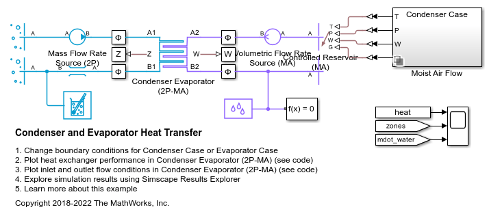
This example models a condenser or an evaporator in simple test setup with R134a refrigerant on the left side and moist air on the right side. It has a cross flow arrangement with the moist air blowing across tube banks filled with the refrigerant.
The Condenser Evaporator (2P-MA) block can operate as either a condenser or an evaporator. In the condenser case, heat flows from the refrigerant to the moist air. This causes the refrigerant to condense from a superheated vapor to a two-phase mixture to a subcooled liquid, resulting in up to three fluid zones along the length of the condenser tubes. In the evaporator case, heat flows from the moist air to the refrigerant. If the moist air is sufficiently wet, water vapor condenses on the surface and is removed from the rest of the moist air flow.
Model

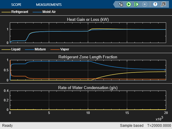
Simulation Results from Scopes

Simulation Results from Simscape Logging
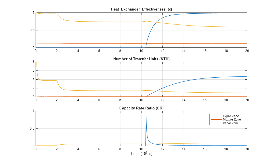
Heat transfer between the refrigerant and the moist air is computed with the  -NTU method. The liquid zone, mixture zone, and vapor zone along the refrigerant tubes have different heat transfer coefficients, heat transfer surface areas, and inlet temperatures. Therefore, the heat exchanger effectiveness, number of transfer units, and the capacity rate ratio are different in each zone. If a zone does not exist, a default value of 0 is shown.

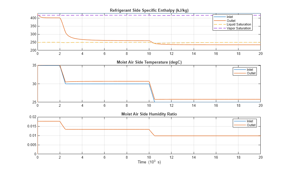
This plot shows the fluid state at the inlets and outlets of the condenser or the evaporator. Liquid, mixture, and vapor zones appears and disappears as the specific enthalpy crosses the saturation boundaries.
