Main Content

Specific Dissipation Heat Exchanger (G-G)

Heat exchanger parameterized by specific dissipation data for systems with two gas flows

Since R2024a

  • Heat Exchanger (G-G) block

Libraries:
Simscape / Fluids / Heat Exchangers / Gas

Description

The Specific Dissipation Heat Exchanger (G-G) block models a gas-gas heat exchanger. The fluids are single phase and each a gas. Neither fluid can switch phase and so, as latent heat is never released, the exchange is strictly one of sensible heat.

Heat Transfer Model

The block heat transfer model depends on the concept of specific dissipation, a measure of the heat transfer rate observed when gas 1 and gas 2 inlet temperatures differ by one degree. Its product with the inlet temperature difference gives the expected heat transfer rate:

Q=ξ(TIn,1TIn,2),

where ξ is specific dissipation and TIn is inlet temperature for gas 1 (subscript 1) or gas 2 (subscript 2). The specific dissipation is a tabulated function of the mass flow rates into the exchanger through the gas 1 and gas 2 inlets:

ξ=f(m˙1,m˙2)

To accommodate reverse flows, the tabulated data can extend over positive and negative flow rates, in which case the inlets can also be thought of as outlets. The data normally derives from measurement of heat transfer rate against temperature in a real prototype:

ξ=QTIn,1TIn,2

The heat transfer model, as it relies almost entirely on tabulated data, and as that data normally derives from experiment, requires little detail about the exchanger. Flow arrangement, mixing condition, and number of shell or tube passes, if relevant to the heat exchanger modeled, are assumed to manifest entirely in the tabulated data.

See the Specific Dissipation Heat Transfer block for more detail on the heat transfer calculations.
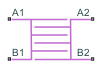
Composite Structure

The block is a composite component. A Specific Dissipation Heat Exchanger Interface (G) block models the gas flow on side 1 of the heat exchanger. Another models the gas flow on side 2. A Specific Dissipation Heat Transfer block captures the heat exchanged across the wall between the flows.

Ports

Conserving

expand all

Opening for gas 1 to enter and exit its side of the heat exchanger.

Opening for gas 1 to enter and exit its side of the heat exchanger.

Opening for gas 2 to enter and exit its side of the heat exchanger.

Opening for gas 2 to enter and exit its side of the heat exchanger.

Parameters

expand all

Heat Transfer

Mass flow rate of gas 1 at each breakpoint in the lookup table for the specific heat dissipation table. The block inter- and extrapolates the breakpoints to obtain the specific heat dissipation of the heat exchanger at any mass flow rate. Interpolation is the MATLAB linear type and extrapolation is nearest.

The mass flow rates can be positive, zero, or negative, but they must increase monotonically from left to right. Their number must equal the number of columns in the Specific heat dissipation table parameter. If the table has m rows and n columns, the mass flow rate vector must be n elements long.

Mass flow rate of gas 2 at each breakpoint in the lookup table for the specific heat dissipation table. The block inter- and extrapolates the breakpoints to obtain the specific heat dissipation of the heat exchanger at any mass flow rate. Interpolation is the MATLAB linear type and extrapolation is nearest.

The mass flow rates can be positive, zero, or negative, but they must increase monotonically from left to right. Their number must equal the number of columns in the Specific heat dissipation table parameter. If the table has m rows and n columns, the mass flow rate vector must be n elements long.

Specific heat dissipation at each breakpoint in its lookup table over the mass flow rates of gas 1 and gas 2. The block inter- and extrapolates the breakpoints to obtain the effectiveness at any pair of gas 1 and gas 2 mass flow rates. Interpolation is the MATLAB linear type and extrapolation is nearest.

The specific heat dissipation values must be not be negative. They must align from top to bottom in order of increasing mass flow rate in the gas 1 channel, and from left to right in order of increasing mass flow rate in the gas 2 channel. The number of rows must equal the size of the Gas 1 mass flow rate vector parameter, and the number of columns must equal the size of the Gas 2 mass flow rate vector parameter.

If your heat exchanger data sheet supplies the heat transfer coefficients, multiply the provided heat transfer coefficients by the surface area to calculate the specific dissipation.

Warning condition for specific heat dissipation in excess of minimum heat capacity rate. Heat capacity rate is the product of mass flow rate and specific heat, and its minimum value is the lowest between the flows. This minimum gives the specific dissipation for a heat exchanger with maximum effectiveness and cannot be exceeded. See the Specific Dissipation Heat Transfer block for more detail.

Gas 1|2

Mass flow rate at each breakpoint in the lookup table for the pressure drop. The block inter- and extrapolates the breakpoints to obtain the pressure drop at any mass flow rate. Interpolation is the MATLAB linear type and extrapolation is nearest.

The mass flow rates can be positive, zero, or negative and they can span across laminar, transient, and turbulent zones. They must, however, increase monotonically from left to right. Their number must equal the size of the Pressure drop vector parameter, with which they are to combine to complete the tabulated breakpoints.

Pressure drop at each breakpoint in its lookup table over the mass flow rate. The block inter- and extrapolates the breakpoints to obtain the pressure drop at any mass flow rate. Interpolation is the MATLAB linear type and extrapolation is nearest.

The pressure drops can be positive, zero, or negative, and they can span across laminar, transient, and turbulent zones. They must, however, increase monotonically from left to right. Their number must equal the size of the Mass flow rate vector parameter, with which they are to combine to complete the tabulated breakpoints.

Absolute temperature established at the inlet in the gathering of the tabulated pressure drops. The reference inflow temperature and pressure determine the fluid density assumed in the tabulated data. During simulation, the ratio of reference to actual fluid densities multiplies the tabulated pressure drop to obtain the actual pressure drop.

Absolute pressure established at the inlet in the gathering of the tabulated pressure drops. The reference inflow temperature and pressure determine the fluid density assumed in the tabulated data. During simulation, the ratio of reference to actual fluid densities multiplies the tabulated pressure drop to obtain the actual pressure drop.

Mass flow rate below which its value is numerically smoothed to avoid discontinuities known to produce simulation errors at zero flow. See the Specific Dissipation Heat Exchanger Interface (G) block for detail on the calculations.

Volume of fluid in the gas 1 or gas 2 flow channel.

Flow area at the inlet and outlet of the gas 1 or gas 2 flow channel. Ports in the same flow channel are of the same size.

Effects and Initial Conditions

Temperature in the gas 1 channel at the start of simulation.

Temperature in the gas 2 channel at the start of simulation.

Pressure in the gas 1 channel at the start of simulation.

Pressure in the gas 2 channel at the start of simulation.

Extended Capabilities

C/C++ Code Generation
Generate C and C++ code using Simulink® Coder™.

Version History

Introduced in R2024a

expand all