3-Way Directional Valve (TL)
3-position directional valve in a thermal liquid network

Libraries:
Simscape /
Fluids /
Thermal Liquid /
Valves & Orifices /
Directional Control Valves
Description
The 3-Way Directional Valve (TL) block represents a valve with three openings in a thermal liquid network, typically between an actuator, pump, and tank. The valve operation is controlled by a single spool displaced according to the signal at port S. You can set the baseline configuration of your valve by specifying the orifices that are open when the spool moves in the positive direction and negative directions in the Positive spool position open connections and Negative spool position open connections parameters, respectively.
You can set the model for valve opening in the Orifice parameterization parameter as a linear relationship or function of user-provided data, which can be applied to one or all flow paths in the valve.
In this configuration, Positive spool position open connections
is set to A-T. When the signal at port S
moves the spool to a positive position, the path between ports A
and T is open to flow. The paths between ports
P and A and between ports
P and T are closed:
In this configuration, Negative spool position open connections
is set to P-A. When the signal at port S
moves the spool to a negative position, the path between ports P
and A is open to flow and the paths between ports
T and A and between ports
P and T are closed:
You can open the path between ports P and T
by setting either Positive spool position open connections or
Negative spool position open connections to
P-T or P-A, A-T, P-T.
A flow path can be open in either the positive or negative spool positions, but not both.
Valve Orifice Parameterizations
The Orifice parameterization sets the method for calculating
the valve open area. The calculations are based either on the orifice parameters or
tabulated data sets specified in the Model Parameterization
tab. The block uses the same data for all flow paths if Area
characteristics is set to Identical for all flow
paths; otherwise, individual values are applied in the
Different for all flow paths setting. The orifice
parameterizations are:
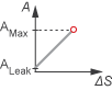
Linear - area vs. spool travelThe opening area is a linear function of the spool travel distance and the signal received at port S:
where:
Amax is the Maximum orifice area.
Aleak is the Leakage area.
ΔSmax is the Spool travel between closed and open orifice.
ΔS is the spool travel distance. For flow paths that are open in the positive position:
and for flow paths that are open in the negative position:
where Sorifice_max is the Spool position at maximum orifice area.
When the valve is in a near-open or near-closed position in the linear parameterization, you can maintain numerical robustness in your simulation by adjusting the Smoothing factor parameter. If the Smoothing factor parameter is nonzero, the block smoothly saturates the opening area between Aleak and Amax. For more information, see Numerical Smoothing.
Tabulated data - Area vs. spool travelProvide spool travel vectors for your system or for individual flow paths between ports P and A, A and T, and P and T. This data will be used to calculate the relationship between the orifice opening area and spool travel distance. Interpolation is used to determine the opening area between given data points. Aleak and Amax are the first and last parameters of the Opening area vector, respectively.

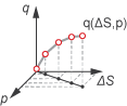
Tabulated data - Volumetric flow rate vs. spool travel and
                            pressure drop
Provide spool travel and pressure drop vectors. The volumetric flow rate is calculated based on the relationship between pressure change and the spool travel distance. Interpolation is used to determine flow rate between given data points. The mass flow rate is the product of the volumetric flow rate and the local density.
When you set Orifice parameterization to
Tabulated data - Mass flow rate vs. spool travel and
                            pressure drop
the block calculates the mass flow rate directly from the control member position and the pressure drop across the valve. The relationship between the three variables can be nonlinear and it is given by the tabulated data in the Spool travel vector, ds, Pressure drop vector, dp, and Mass flow rate table, mdot(ds,dp) parameters.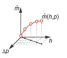
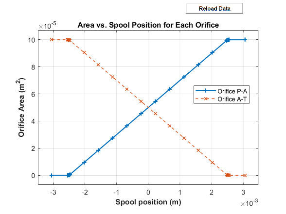
Visualize Orifice Openings
To generate a characteristic plot of the valve, click the Plot button next to Valve characteristics. The plot shows the orifices selected in the Valve Configuration settings. The parameterization selection sets the axes, which are either:
Orifice area versus spool position
Volumetric flow rate versus spool position, queried at a specific pressure differential
Mass flow rate versus spool position for the reference inflow temperature and reference inflow pressure, queried at a specific pressure differential
To update the data after changing the block parameters, click Reload Data on the figure window.
This image shows an example valve configuration. In the Valve Configuration settings:
Positive spool position open connections is
P-A.Negative spool position open connections is
A-T.
All other spool positions are at the default values.
Faults
To model a fault, in the Faults section, click the Add fault hyperlink next to the fault that you want to model. Use the fault parameters to specify the fault properties. For more information about fault modeling, see Introduction to Simscape Faults.
The Spool position when faulted parameter has three fault options:
Positive— The spool position freezes in the positive position, and the flow paths specified by the Positive spool position open connections parameter open to their maximum value. The flow paths specified by the Negative spool position open connections parameter are closed.Negative— The spool position freezes in the positive position, and the flow paths specified by the Negative spool position open connections parameter open to their maximum value. The flow paths specified by the Positive spool position open connections parameter are closed.Maintain last value— The valve freezes at the spool position when the trigger occurs.
Due to numerical smoothing at the extremes of the valve area, in the linear parameterization, the minimum area that he block uses is larger than the Leakage area, and the maximum is smaller than the Maximum orifice area, in proportion to the Smoothing factor value. For more information, see Numerical Smoothing.
After the fault triggers, the valve remains at the faulted area for the rest of the simulation.
Assumptions
Fluid inertia is ignored.
Spool loading due to inertial, spring, and other forces is ignored.
All valve orifices are assumed to be identical in size unless otherwise specified.
Examples
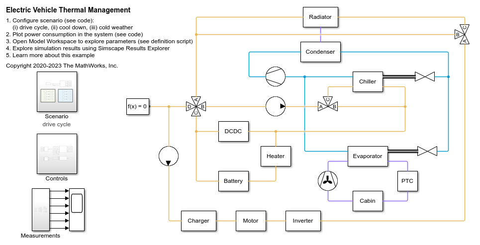
Electric Vehicle Thermal Management
Model the thermal management system of a battery electric vehicle.