Get Started with Simulink HDL Cosimulation for Synopsys VCS
This example shows how to cosimulate an HDL design with Simulink® and the Synopsys® VCS® simulator. It uses a raised cosine filter written in Verilog®. Digital communications systems commonly use the raised cosine filter as a pulse shaping filter. It prevents inter-symbol interference (ISI) for modulated pulse inputs.
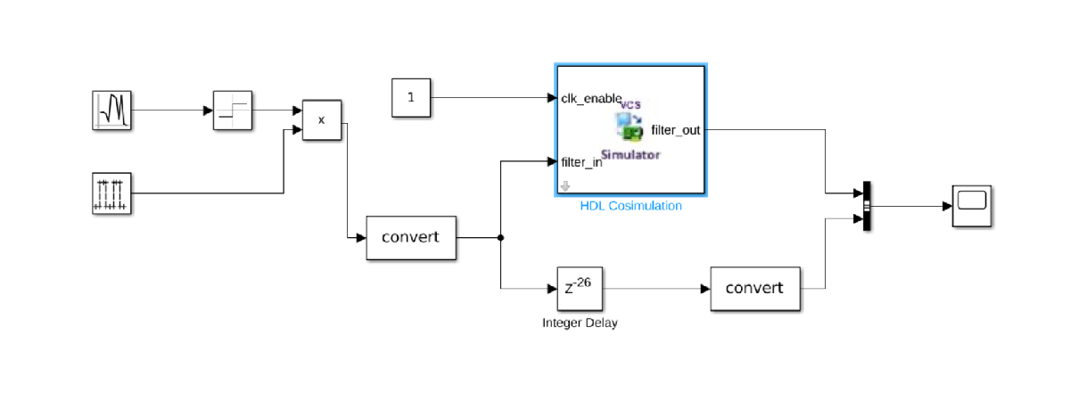
To verify the functionality of the raised cosine filter in this example, you use a Simulink testbench. For this testbench, you use the launchVCS function to generate HDL compile scripts and HDL simulator launch scripts, and then execute them. After adding the HDL Cosimulation block from the Simulink library, you connect it to your testbench. The testbench generates input to the HDL design under test and plots the waveforms of both input and output. During simulation, you observe the input and output waveforms of the HDL filter in Simulink.
Requirements
In addition to HDL Verifier™ and Simulink, this example requires the VCS simulator from Synopsys.
Open Model and Simulator
For this example, the rcosflt_tb_vcs.slx model already includes the HDL Cosimulation block. To add the HDL Cosimulation block to your own Simulink testbench model, perform the following steps.
Open your testbench model.
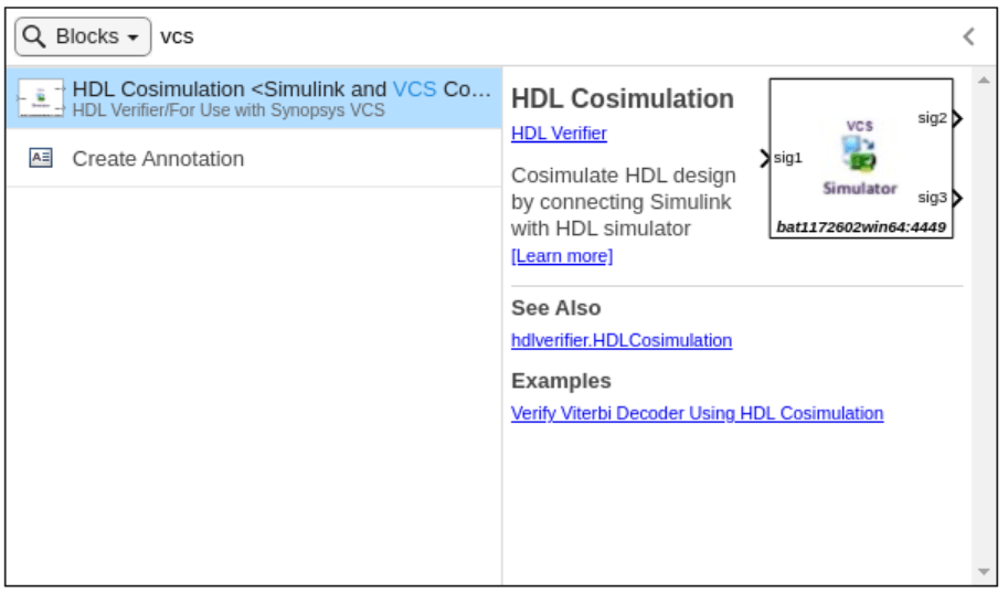
Double-click the Simulink canvas and search for "VCS Cosimulation". Then, add the HDL Cosimulation block by double-clicking the search result.
Run this script at the MATLAB® command prompt:
% Open Simulink testbench
open_system('rcosflt_tb_vcs.slx');
% Run launchvcs command to launch Synopsys VCS simulator in CLI mode
launchVCS(VerilogFiles= "rcosflt_rtl.v", ...
    HDLTopLevelName= "rcosflt_rtl", ...
    RunMode= "cli", ...
    PreSimulationTcl= {
    'force rcosflt_rtl.clk 1 0, 0 10 -repeat 20', ...
    'force rcosflt_rtl.reset 1 0, 0 15'} ...
    );
#### Starting the HDL simulator for an Cosimulation Simulink link session.
#### Applying communication settings to the cosim block list...
#### Generating compilation and run scripts...
#### Compiling HDL...
#### Launching HDL simulator...
Successfully ran launch script.
#### Done.
The script performs these actions:
Opens the
rcosflt_tb_vcs.slxtestbench model.Starts the Synopsys VCS simulator in an interactive shell.
Generates the
cosimVCS.compile.bashcompile script and thecosimVCS.launch.bashlaunch script. These scripts set up the GCC environment and load the HDL Verifier library into the Synopsys VCS simulator.
The launchVCS command uses the following properties.
VerilogFiles — Specifies the HDL design file
rcosflt_rtl.v.HDLTopLevelName — Specifies the name of the HDL top-level module
rcosflt_rtl.RunMode — Starts the simulator in an interactive shell.
PreSimulationTcl — Generates waveforms for the signals
clkandreset. Generating these waveforms before the start of HDL simulations eliminates the need to create a separate Simulink model or HDL testbench logic to drive the design block.
Connect to Simulink
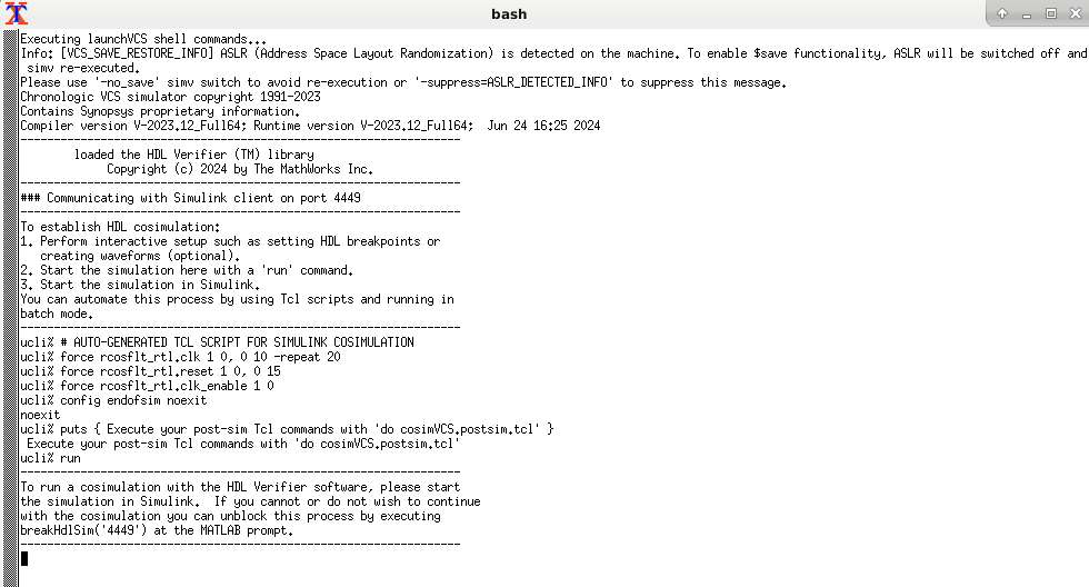
Establish the connection between the simulator and Simulink by running this command in the shell.
ucli% run
The shell displays a log with instructions.
Set Block Parameters
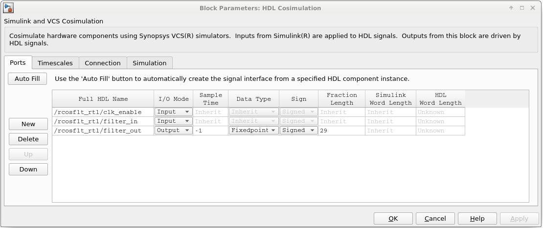
In the rcosflt_tb_vcs model, double-click the HDL Cosimulation block. On the Ports tab, set the input and output ports to the values shown in the following figure.
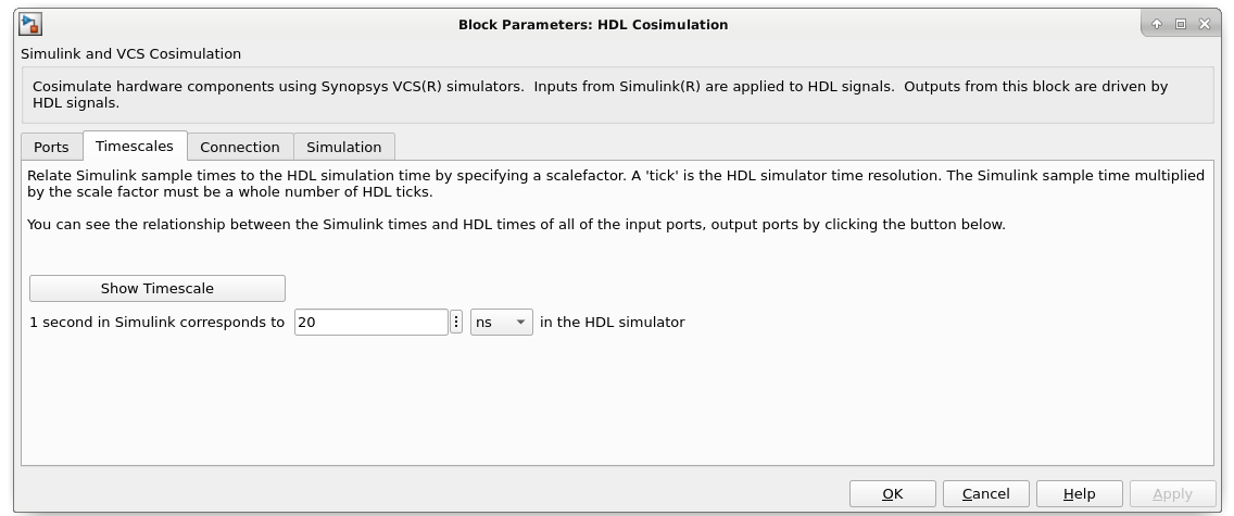
On the Timescales tab, set 1 second in Simulink corresponds to 20 ns.
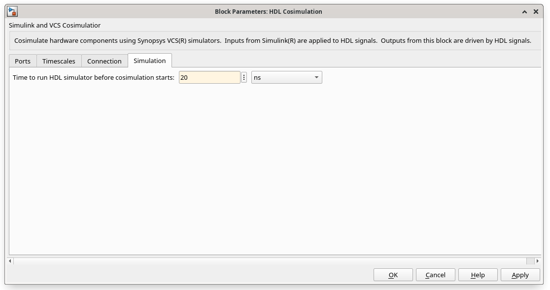
On the Simulation tab, set Time to run HDL simulator before cosimulation starts to 20 ns.
Click OK and connect the signals to the HDL Cosimulation block.
Run Cosimulation
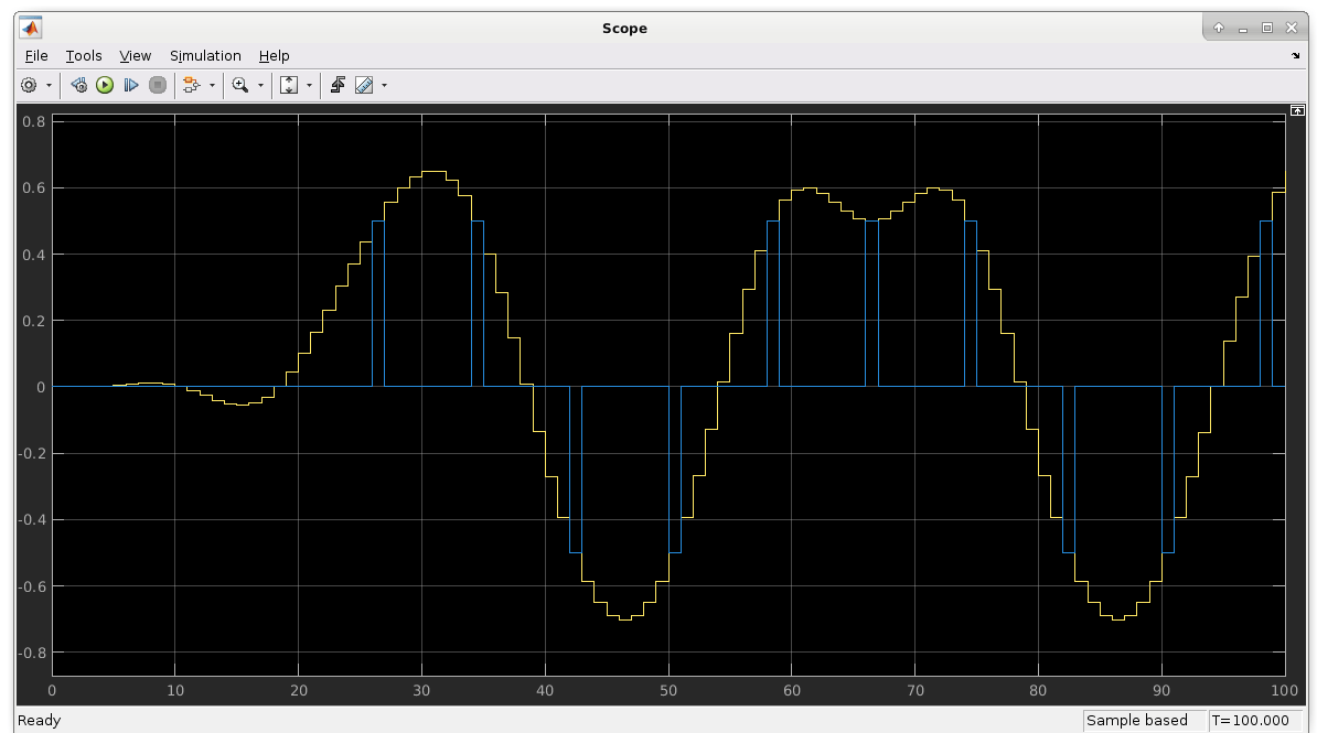
Now run the simulation. The scope displays both the delayed version of the input to the raised cosine filter and the filter's output. If you sample the output of this filter directly, no inter-symbol interference occurs.
