Generate SystemVerilog DPI Component
Step 1. Select Target
Open your model, and on the Apps tab, click HDL Verifier. Then, on the HDL Verifier tab, click C Code Settings. The Configuration Parameters dialog opens on the Code Generation pane.
At System target file, under Target Selection, click Browse. Select
systemverilog_dpi_grt.tlcfrom the list.Alternatively, if you have an Embedded Coder® license, you can select target
systemverilog_dpi_ert.tlc. This target enables you to access its additional code generation options on the Code Generation pane of the Model Configuration Parameters dialog box.If you are generating a cross-platform component, you must select
systemverilog_dpi_ert.tlcfor the System target file parameter.
Step 2. Select Toolchain
Still on the Code Generation pane, select a Toolchain. To generate a shared library for the same operating system as the host machine, select a compiler from the list of installed compilers. Supported options are:
Siemens® Questa™ or ModelSim™
AMD® Vivado® simulator
Cadence® Xcelium™ (Linux® only)
Synopsys® VCS® (Linux only)
To automatically set the toolchain, select Automatically locate an
installed toolchain.
You can optionally add additional compilation flags. Under Build
Configuration, select Specify. To display
the current flags, click Show Settings.
Step 3. Enable Test Point Access (Optional)
Complete this step if you designated internal signals in your model as test points and want to access them in the generated DPI component.
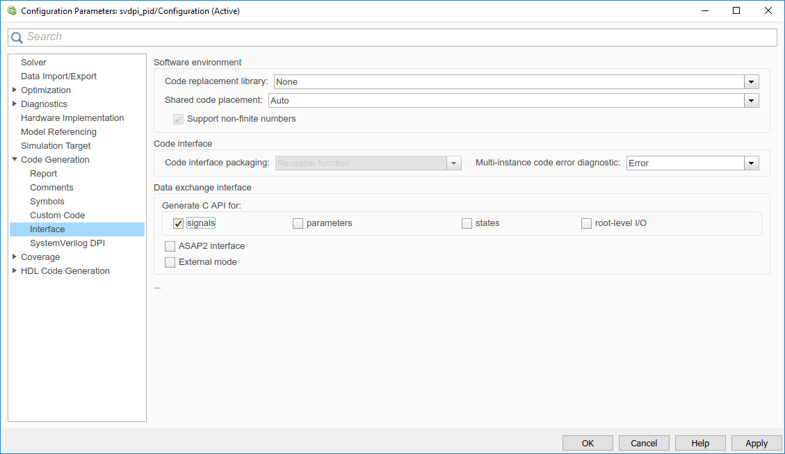
In the left pane, select Code Generation > Interface.
In the Generate C API for section, verify that the signals check box is selected.

Select Code Generation > SystemVerilog DPI.
For Generate access function to test point, select
One function per Test PointorOne function for all Test Points.
Step 4. Configure SystemVerilog Generation Options
In the left pane, select Code Generation > SystemVerilog DPI.
Select Report run-time error to export run-time errors from Simulink® to your HDL simulation. Not all Simulink blocks provide run-time error checks. You can add run-time checks by adding an Assertion block to your Simulink model.
Select Generate test bench to generate a testbench. The testbench checks the generated C component against data vectors from your Simulink subsystem.
In the SystemVerilog Ports section, set these parameters.
Select the SystemVerilog data types. (optional)
Set Connection to
Port listorInterface.Set Composite data type to
Structure. This option creates SystemVerilogstructdata types for any nonvirtual buses or for complex data types. Alternatively, selectFlattenedto create flattened ports.Select Scalarize matrix and vector ports to create multiple SystemVerilog scalar ports from a Simulink vector or array. Clear this option to preserve arrays on the interface.
If your design is sequential and registered, set Component template type to
Sequential. If your model is purely combinational (with no clock delays), set Component template type toCombinational.
Tip
When using HDL Coder™ for code generation, match the generated interface by selecting the following options:
Set Ports data type to
Logic Vector.Set Composite data type to
Flattened.Select Scalarize matrix and vector ports.

Click OK to accept these settings and to close the Configuration Parameters dialog box.
Step 5. Generate SystemVerilog DPI Component
In your model, right-click the block containing the subsystem you want to generate the component from. Select Code > C/C++ Code > Build this Subsystem.
Click Build in the dialog box.
The SystemVerilog component is generated as
subsystem_build/subsystem_dpi.svsubsystemis the name of the subsystem from which you generated the DPI component. This build also results in a generated package file namedsubsystem_build/subsystem_dpi_pkg.sv
If you built the component for the host machine, you can now use the component. To copy the built component to another machine with the same operating system, copy these files:
Shared library,
subsystem.so, orsubsystem_win64.dllGenerated SystemVerilog wrapper,
subsystem_dpi.svGenerated SystemVerilog package file,
subsystem_dpi_pkg.svGenerated testbench folder,
dpi_tb(optional)
To port the component to another machine with a different operating system, follow the instructions in Generate Cross-Platform DPI Components.