Generate HDL Code Using HDL Coder Native Floating Point and AMD Floating Point Library IP
This example shows how to create a model design that uses both HDL Coder™ native floating-point (NFP) and AMD® floating-point IP. You can use this mixed-design approach to accommodate larger and more complex designs into the FPGA fabric. You can use this hybrid design with AMD floating-point libraries on AMD devices such as Versal, Zynq® UltraScale+™, and more.
Prepare a Model to Use Vendor Specific AMD Floating-Point Library IP
1. To use AMD floating-point library, set the synthesis tool to Xilinx Vivado and set the tool path for your synthesis tool using hdlsetuptoolpath function.
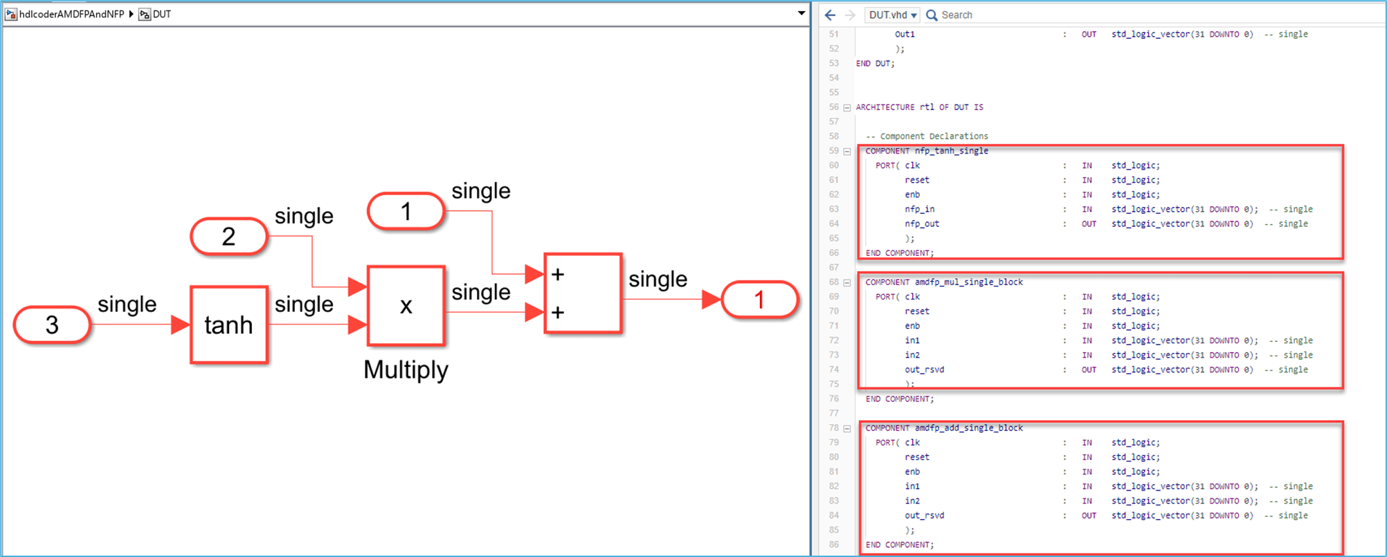
2. Open the Simulink® model, hdlcoderAMDFPAndNFP. The model consists of a Tanh, Multiply, and Add block. The input data type is single.
open_system('hdlcoderAMDFPAndNFP.slx')
3. Open the Configuration Parameters dialog box. In the HDL Code Generation > Target pane, select the target device and family. Make sure that Synthesis Tool is set to Xilinx Vivado.
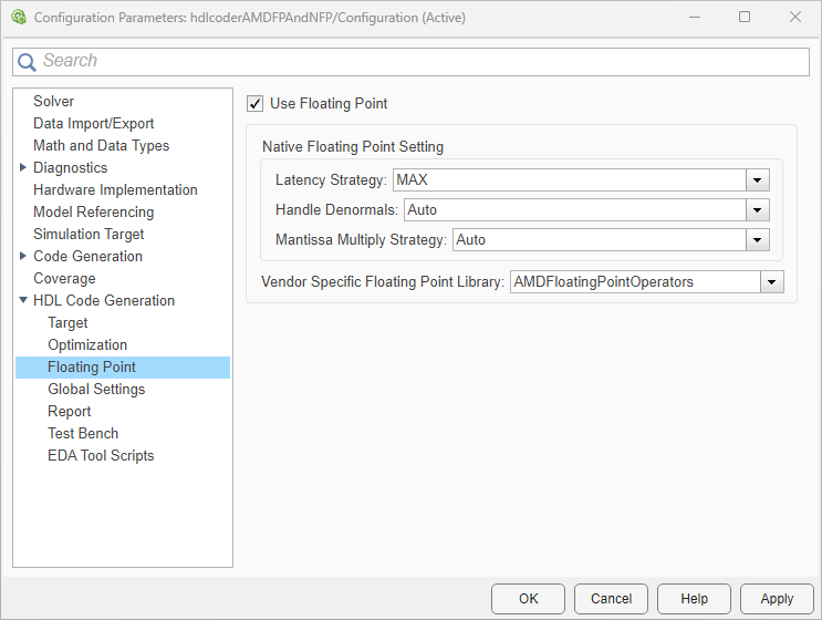
4. In the Floating Point pane, select Use Floating Point to map the design to the native floating-point library. To map the design to a AMD floating point library, set the Vendor Specific Floating Point Library to AMDFloatingPointOperators.
Click OK to save the changes.

5. In the Test Bench pane, set the Simulation library path of the simulation tool.
6. To simulate your design in ModelSim® Simulator, you must compile the simulation library in Vivado® environment. Open the Vivado tool, in the Tools menu,select Compile Simulation Libraries. In the Compile Simulation Libraries settings, set the Compiled library location, Simulator executable path and GCC executable path, and compile the simulation libraries.
Generate HDL Code and Testbench
1. Generate HDL code for the DUT subsystem, hdlcoderAMDFPAndNFP/DUT, by using the makehdl function.
makehdl('hdlcoderAMDFPAndNFP/DUT');
2. Generate the test bench for the Simulink model.
makehdltb('hdlcoderAMDFPAndNFP/DUT');
After makehdl runs,the HDL Code pane opens and displays the VHDL code for the components of the model. The generated DUT.vhd file shows the trigonometric function component tanh maps to a native floating-point component, and the Multiply and Add components map to AMD floating-point components.

3. Open the generated model file gm_hdlcoderAMDFPAndNFP.slx. The blocks that map to native floating-point components are light blue and display NFP on the block mask. The blocks that map to the AMD floating point components are cyan and have initials AMD associated on the block mask. For Versal® devices, floating-point operators such as multipliers and adders are mapped to DSPFP32 FPGA resources, such as hardened DSP floating-point adder and multiplier primitives. For other AMD device families, the generated HDL code uses the full DSP mode to map the operators to the AMD floating-point IPs.
HDL Coder adds matching delays to balance the added latency from the floating-point operator blocks. Double-click the floating-point block to see the latency added for each. For more information on latency with floating-point operators, see Latency Considerations with Native Floating Point.

You can customize the IP settings of the AMD floating-point target library by using the hdlcoder.FloatingPointTargetConfig object. For more information, see Customize Floating-Point IP Configuration.
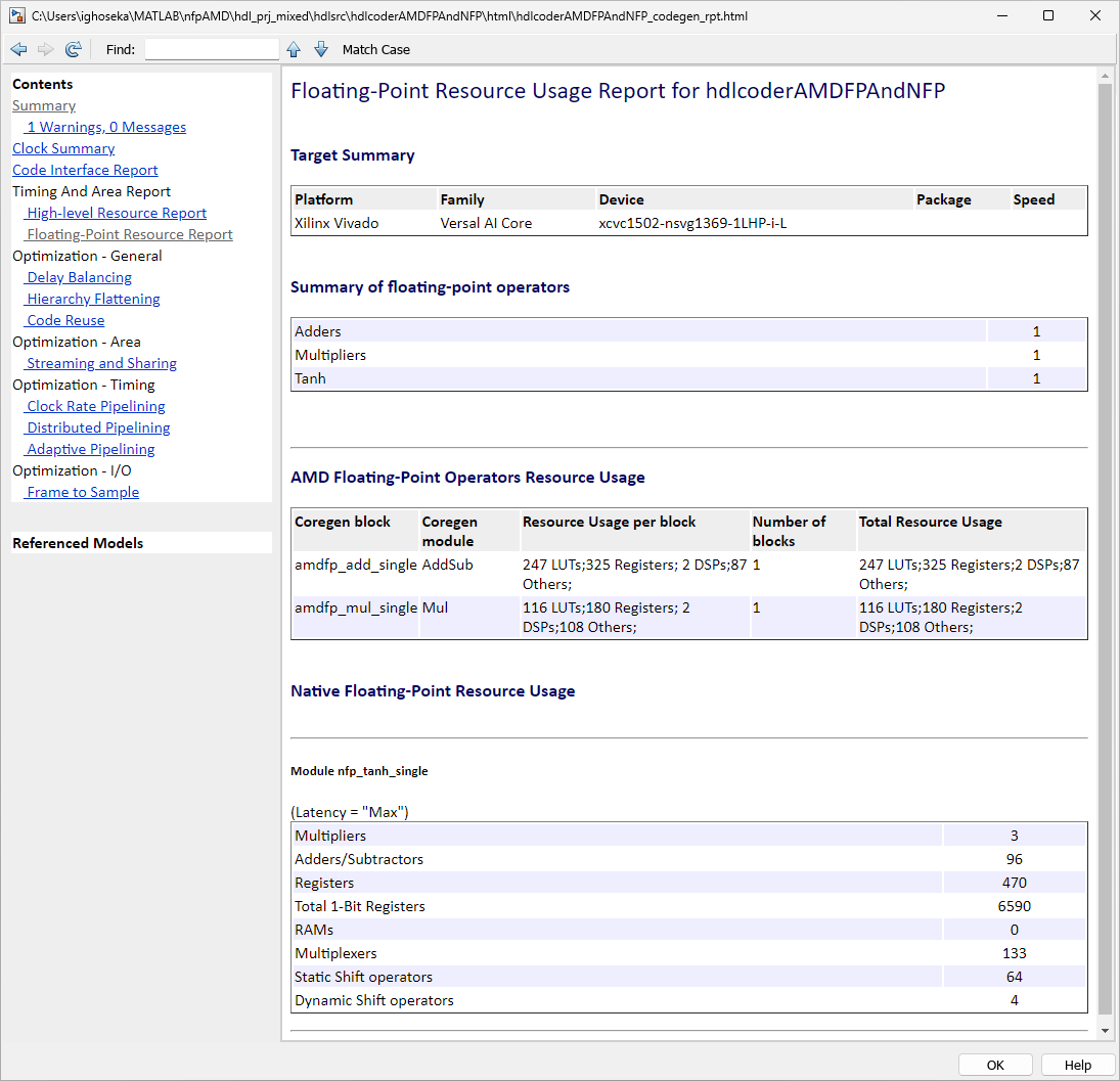
4. HDL Coder generates the code generation reports for the model. In the code generation report, open the Floating-Point Resource Report to view the summary of the floating-point resource usage.

Verify Functionality by Using ModelSim Simulation
The makehdltb function generate these files to simulate your design in ModelSim® software.
DUT_tb_compile.dofile compiles generated HDL files and loads the entity to be tested (DUT.vhd) and its test bench code (DUT_tb.vhd).DUT_tb_sim.dofile initializes the simulator, set up wave window signal displays, and run a simulation.
To simulate your design in ModelSim software:
Open ModelSim software and navigate to the folder containing the DO files.
Run the DO files in this order:
do DUT_tb_compile.do
do DUT_tb_sim.do
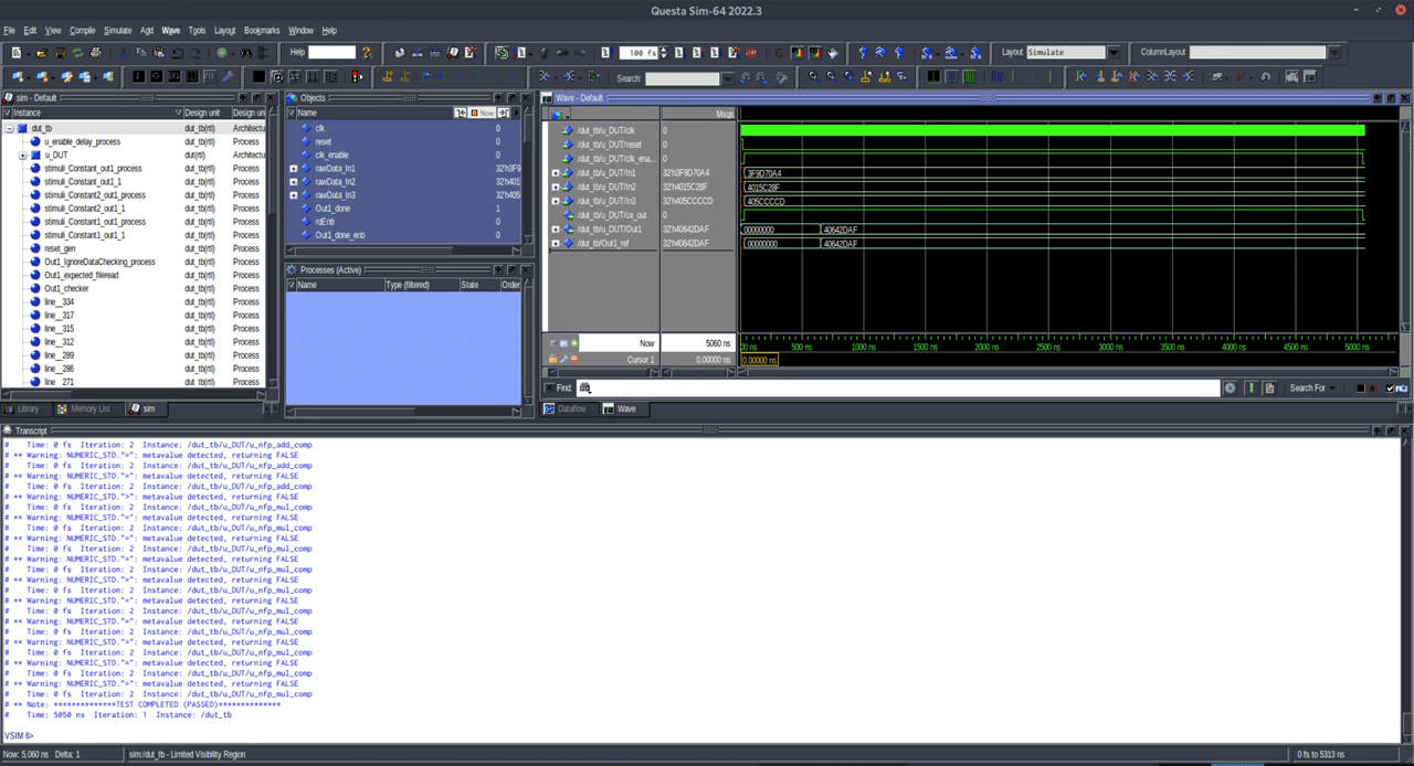
You can view ModelSim simulation with the a message at the end of the log to indicate that the tests passed.

Design Synthesis in Xilinx Vivado
To perform design synthesis of the mixed NFP and AMD floating-point design in Xilinx® Vivado® software, follow these steps:
Open Xilinx Vivado and create a project.
Add the generated HDL files to the Vivado project, including the top module DUT and the other supporting files.
Set
DUTas top module in the Vivado project.Perform design synthesis by following the Xilinx Vivado workflow.
See Also
Vendor Specific Floating Point Library | HDL Coder Support for FPGA Floating-Point Library Mapping