Model References in Fixed-Point Tool Workflows
When your model contains a model reference, or a reference to another model using a Model block to create a model hierarchy, there are additional limitations and best practices to consider when working with automated fixed-point conversion workflows in the Fixed-Point Tool. The next section, Considerations for Working with Model References in Fixed-Point Conversion Workflows, describes some of these considerations. The following example, Convert a Model Reference to Fixed Point, shows how to convert a model reference to fixed point using the iterative fixed-point conversion workflow in the Fixed-Point Tool.
Considerations for Working with Model References in Fixed-Point Conversion Workflows
System Under Design (SUD) Selection for Model Reference Hierarchies
When working with model references, the context is specific to the model reference under selection, not the top-level parent model. The Fixed-Point Tool works similarly. If you open the tool from a block inside a model reference, the tree shown in the Model Hierarchy pane of the tool displays the tree in the context of the model reference, rather than the top-level model. Instead of converting a subsystem in a model reference directly, use the top-level model as a test harness. Open the tool from the top-level parent model, navigate to the subsystem in the model reference, and select this as the SUD.
In the Fixed-Point Tool, you cannot select a model reference used inside a Variant Subsystem as the system under design. To avoid this limitation, try one of these workarounds:
Place the model reference in a subsystem and then select that subsystem as the SUD in the Fixed-Point Tool.
Directly select the model reference as the SUD in the Fixed-Point Tool.
Hardware Implementation Settings Consistency
Hardware implementation settings must be consistent throughout the model hierarchy of the model containing the system under design. the Fixed-Point Tool screens for this requirement in the Hardware Implementation Consistency preparation check.
Fixed-Point Instrumentation and Data Type Override Settings for Model Reference Hierarchies
When you simulate a model that contains model references, the data type override and fixed-point instrumentation settings for the top-level model do not control the settings for the model references. You must specify these settings separately for the model reference. If the settings are inconsistent, for example, if you set the top-level model data type override setting to double and the model referenced to use local settings and the model reference uses fixed-point data types, data type propagation issues might occur.
You can define custom data type override settings using
set_param. For an example, see Use Custom Data Type Override Settings for Range Collection.
When you change the fixed-point instrumentation and data type override settings for any instance of a model referenced, the settings change on all instances of the model and on the model reference itself.
MATLAB Function Blocks Used in Model References
Instrumentation is not supported for MATLAB Function blocks used inside a model reference. As a result, the Fixed-Point Tool does not collect or report logged data in the report for MATLAB Function blocks used inside a model reference.
When a MATLAB Function block is used inside a model reference and you select the top-level model as the system under design (SUD), the Fixed-Point Tool does not convert the MATLAB Function block used inside the model reference. Similarly, the Function Replacement in the Fixed-Point Tool feature does not display unsupported functions for MATLAB Function blocks used inside a model reference.
Range Collection for Model Blocks in Normal Mode Only
The Fixed-Point Tool logs simulation minimum and maximum values only for instances of the model reference that are in normal mode. It does not log simulation minimum and maximum values for instances of the model reference that are in non-normal modes. If your model contains multiple instances of a model reference and some are instances in normal mode and some are not, the tool logs and displays data for those that are in normal mode.
Derived Range Analysis for Model Blocks
Derived range analysis is supported for Model blocks, with some limitations. See Limitations of Support for Model Blocks for more information.
How the Fixed-Point Tool Proposes Data Types for SUD Containing Model Reference
When the system under design (SUD) contains a model reference, the Fixed-Point Tool proposes data types for the objects in the model reference based on ranges collected through simulation or derived range analysis, depending on your range collection mode selection. If the system under design contains several instances of the same model reference, the Fixed-Point Tool uses a union of the collected ranges for data type proposals.
Systems that share data types across model reference boundaries may get data type propagation errors. See Data Type Propagation Errors After Applying Proposed Data Types for tips on avoiding these errors.
Convert a Model Reference to Fixed Point
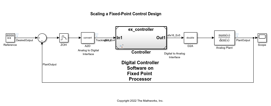
Open ex_mdlref_controller Model
Open the ex_mdlref_controller model. The model contains a Model block that references a model of a controller.
open_system('ex_mdlref_controller')
View Model Hierarchy in Fixed-Point Tool
Open the Fixed-Point Tool. On the Simulink® Apps tab, under Code Generation, click the app icon.
This example uses the iterative fixed-point conversion workflow in the Fixed-Point Tool. To start the workflow, in the Fixed-Point Tool, select Iterative Fixed-Point Conversion.
In the Fixed-Point Tool, the Model Hierarchy pane displays a subnode for the instance of the model reference,
Controller (ex_controller), and a node for model being referenced,ex_controller.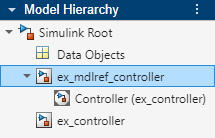
Next, in the
ex_mdlref_controllermodel, create a copy of the Model blockControllerso thatex_mdlref_controllercontains two instances of the model referenceex_controller. Save the changes to the model.Restart the Fixed-Point Tool and Iterative Fixed-Point Conversion to reflect the model changes in the tool.
The Fixed-Point Tool now displays a subnode for each instance of the model reference,
Controller (ex_controller)andController1 (ex_controller).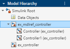
Collect and View Simulation Ranges for Model References
In the Fixed-Point Tool, under System Under Design (SUD), select
ex_controlleras the system to convert.Under Range Collection Mode, select Simulation Ranges.
In the toolstrip, click Prepare.
The Fixed-Point Tool checks the system under design for compatibility with the conversion process and reports that the model is ready for conversion.
Expand the Collect Ranges button arrow and select
Double precision. This option instructs the tool to override data types in the models with doubles during the range collection simulation.Click the Collect Ranges button to start the range collection simulation.
The tool logs and displays the results for each instance of the model reference. For example, here are the results for the first instance of the model reference
ex_controller.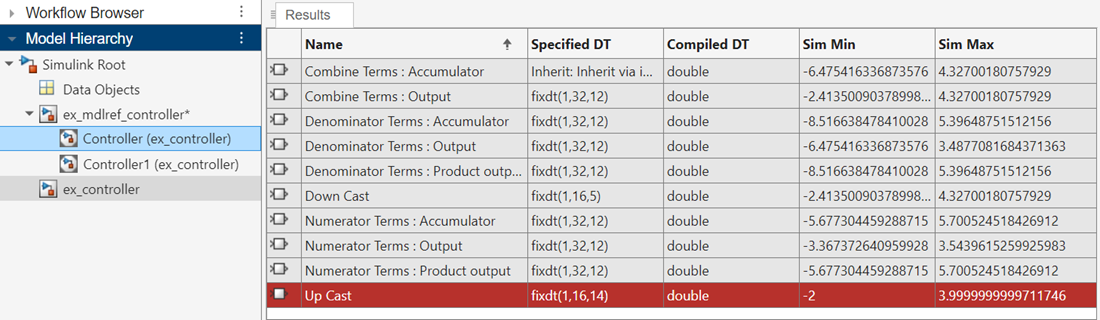
Here are the results for the second instance of
ex_controller.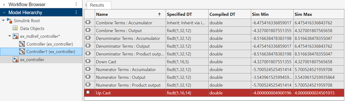
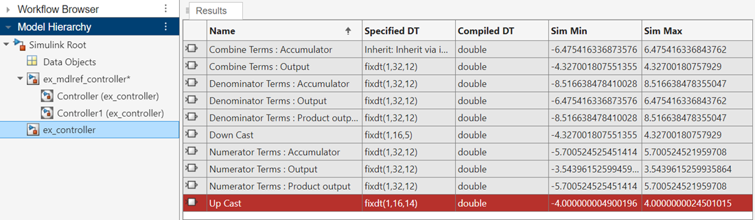
In the model reference node, the tool displays the union of the results for each instance of the model reference.
Propose Data Types for a Model Reference
In the Convert section of the toolstrip, click Settings. Specify the Safety margin for simulation min/max (%) parameter as
20. This setting instructs the tool to multiply the values collected in the range collection simulation by a factor of 1.2. For more information on this parameter, see the description under Fixed-Point Tool Settings.Click Propose Data Types.
The Fixed-Point Tool uses the collected range information to propose data types for each block such that the precision is maximized while the full range of simulation values, including the added safety margin, is spanned. The tool displays the proposed scaling in the spreadsheet.
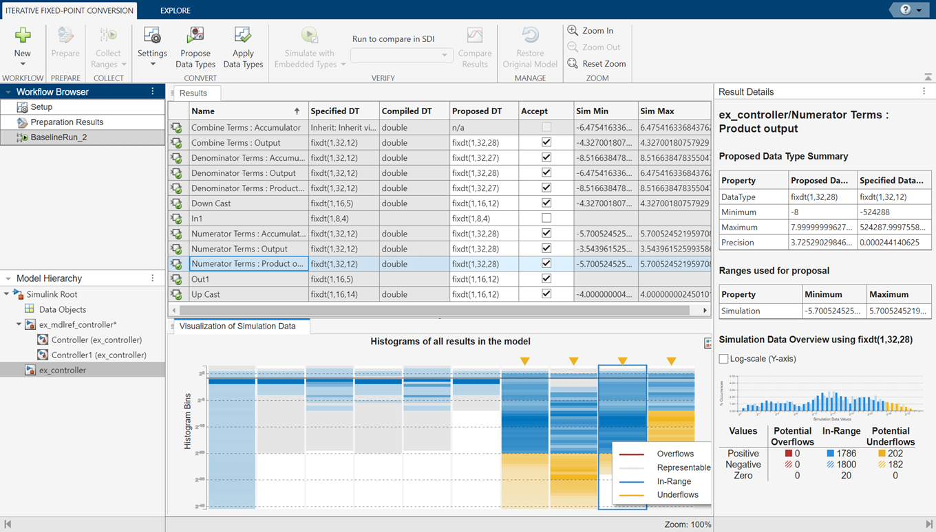
Review the proposed data types in the Results spreadsheet. To view more information about a data type proposal, select the row in the spreadsheet and view details in the Result Details pane.
You can choose to accept data type proposals by selecting the Accept check box. By default, the Fixed-Point Tool accepts all data type proposals that differ from the current settings. For this example, verify that the Accept check box is selected for each block in the Controller system.
Click Apply Data Types to apply the data type proposals that you accepted in the previous step.
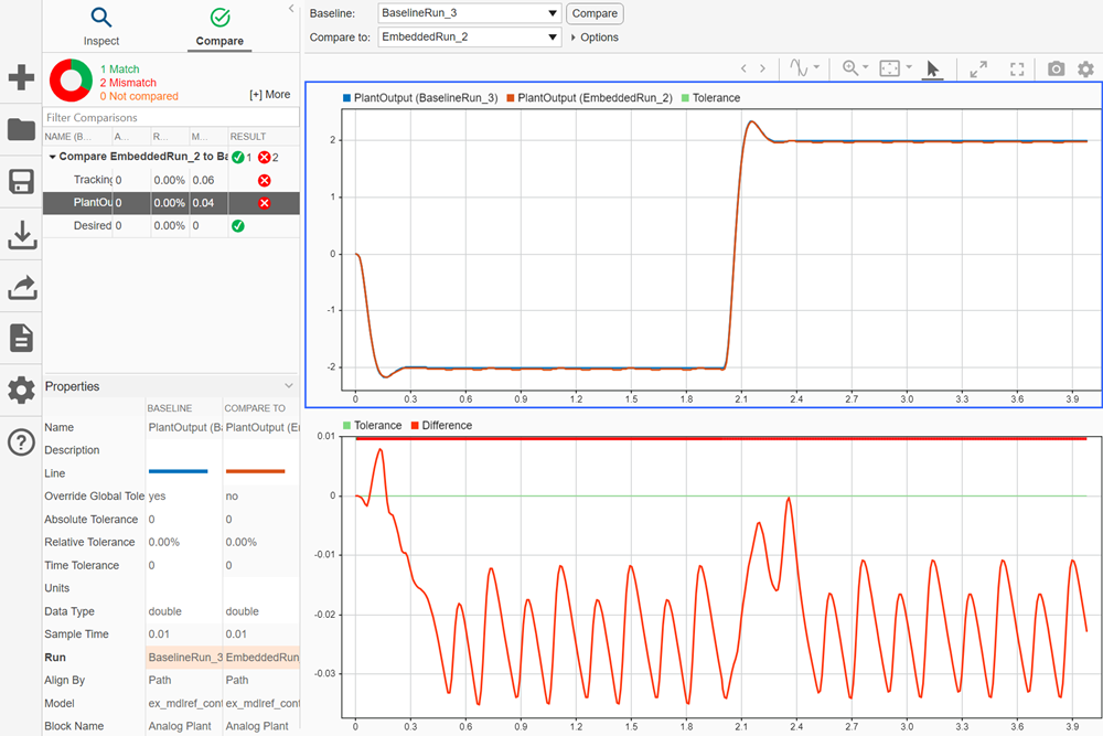
In the Verify section of the toolstrip, click the Simulate with Embedded Types button. The tool simulates the model using the newly applied data types and stores the results in
EmbeddedRun.Click Compare Results. The Simulation Data Inspector plots the Analog Plant output for the floating-point and fixed-point runs and the difference between them.