Configure Model Data Interface for C Code Generation
To integrate the generated code with external code or to generate code that complies with coding standards and guidelines, you can configure how data elements in a model, such as block parameters and signals lines, appear in the generated code. You can configure default code generation settings for categories of data elements and configure individual elements by using the Code Mappings editor or code mappings API. For example, you can configure settings that:
Control placement of declarations and definitions in generated and external (exported and imported) files.
Package multiple data items into structures.
Apply storage type qualifiers
constandvolatile.
This example shows how to configure data elements for code generation for example model ConfigurationInterface.
Explore Example Model
Open example model ConfigurationInterface.
model = 'ConfigurationInterface';
open_system(model)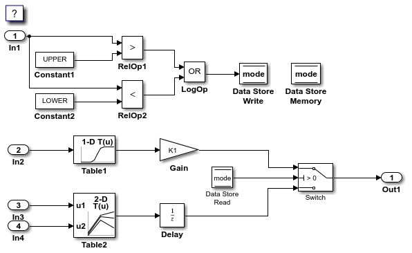
The example shows how to configure these model data elements for code generation:
InportblocksIn1,In2,In3, andIn4Outport block
Out1Model parameter arguments
LOWERandUPPERModel parameters
K1,Table1, andTable2Local data store
modeSignal lines sourced from lookup table blocks
Table1andTable2State
X(delay)
Configure Default Settings for Inport Blocks
Open the Embedded Coder app.
In the C Code tab, select Code Interface > Default Code Mappings.
In the Code Mappings editor, under Inports and Outports, select category Inports. Set the default storage class to
ImportFromFile.In the Property Inspector, set Header File to
exInDataLut.h.
Configure Default Settings for Outport Block
On the Data Defaults tab, under Inports and Outports, select category Outports. Set the default storage class to
ExportToFile.In the Property Inspector, set Header File to
exOutSys.hand Definition File toexOutSys.c.
Configure Default Settings for Parameters
On the Data Defaults tab, under Parameters, select category Model parameter arguments. Leave the storage class set to
Default. With that setting, the code generator allocates a separate area of memory for each argument instance.Select category Model parameters. Link text
'Auto' will be inlinedindicates that the code generator is configured to inline model parameters by default. For this example, configure the model parameters to be tunable. Click'Auto' will be inlined. The Model Configuration Parameters dialog box opens.Set model configuration parameter Default parameter behavior to
Tunable. Save the change and close the dialog box. In the Code Mappings editor, the link text changes to'Auto' will be tunable.In the Code Mappings editor, with the Model parameters category selected, set the storage class to
ConstVolatile.
Configure Default Settings for Signals, States, and Data Stores
On the Data Defaults tab, under Signals, select category Signals,states, and internal data. Set the default storage class to FileScope.
Configure default code mappings for shared local data stores. Select category Shared local data stores. Set the storage class to
Volatile.Save the model.
Configure Code Generation Settings for Individual Inport Blocks
In the Code Mappings editor, click the Inports tab. The editor lists the names of root-level
InportandIn Bus Elementblocks that are in the model. If a port resolves to a signal object, a resolve-to-signal-object icon appears to the right of the element name. The storage class for each inport is set toAuto, which means that the code generator might eliminate relevant code for optimization purposes. If optimizations are not possible, the code generator applies the model default configuration. For this example, the model default configuration specifies storage classImportedFromFile. To avoid avoid optimizations and force the code generator to use the default configuration, set the storage class toModel default. To override the default configuration, specify the storage class that meets the code generation requirements for that inport.Configure the code generator to apply the default storage class setting to inports
In2,In3, andIn4. Select the rows for the three inports. Then, for one of the selected inports, set the storage class toModel default: ImportFromFile. The storage class for the three selected inports changes to Model default: ImportFromFile.For inport
In1, override the default storage class setting. Set the storage class toImportFromFile. In the Property Inspector, set Header File toexInDataMem.h.Configure code identifiers for the inports so that the variables in the generated code match the interface names in the external header and definition files. In the Code Mappings editor, select the row for each inport. In the Property Inspector, set the Identifier property to these values:
input1,input2,input3, andinput4.
Configure Code Generation Settings for Individual Outport Blocks
In the Code Mappings editor, click the Outports tab. The editor lists the names of root-level
OutportandOut Bus Elementblocks that are in the model. If a port resolves to a signal object, a resolve-to-signal-object icon appears to the right of the element name. The storage class for the outport in the example model is set toAuto, which means that the code generator might eliminate relevant code for optimization purposes.To avoid optimizations and force the code generator to use the default configuration, set the storage class to
Model default: ExportToFile. The storage class for the selected outport changes toModel default: ExportToFile.Configure the code identifier for the outport so that the variable in the generated code matches the interface name used by the external code. In the Code Mappings editor, select the row for the outport. In the Property Inspector, set the Identifier property to
output.
Configure Code Generation Settings for Individual Parameters
In the Code Mappings editor, click the Parameters tab. Expand Model Parameter Arguments. By default, the storage class for each model parameter argument is set to
Auto, which means that the code generator might eliminate relevant code for optimization purposes. If optimizations are not possible, the code generator applies the model default configuration. For this example, leave the storage class set toAuto.Expand Model Parameters. By default, the storage class for each model parameter is set to
Auto. For this example, you want to avoid optimizations and for the code generator to use the default storage class setting, ConstVolatile.In the Code Mappings editor, under Model Parameters, select parameters
K1,Table1, andTable2. Set the storage class toModel default: ConstVolatile.Configure the code identifiers for model parameters with names that include the prefix
mp_, as the requirements specify. In the Code Mappings editor, select model parameterK1. In the Property Inspector, expand the Code node. Set the storage class property Identifier tomp_K1. For parametersTable1andTable2, set Identifier tomp_Table1andmp_Table2.
Configure Code Generation Settings for Individual Data Stores
In the Code Mappings editor, click the Data Stores tab. Expand Local Data Stores. The storage class for data store mode is set to Auto, which means that the code generator might eliminate relevant code for optimization purposes. For this example, you want to avoid optimizations and for the code generator to use the default storage class setting,
Volatile.In the Code Mappings editor, select local data store
mode. Set the storage class toModel default: Volatile.Configure the code identifier for the data store with a name that includes the prefix
ds_. In the Code Mappings editor, select shared local data storemode. In the Property Inspector, expand the Code node. Set the storage class property Identifier tods_mode.
Configure Code Generation Settings for Individual States
In the Code Mappings editor, click the Signals/States tab. Expand States. The storage class for the state is set to
Auto, which means that the code generator might eliminate relevant code for optimization purposes. For this example, you want to avoid optimizations and for the code generator to use the default storage class setting,FileScope.In the Code Mappings editor, select state
X. Set the storage class toModel default: FileScope.Configure the code identifier for the state with a name that includes the prefix
dstate_, as the requirements specify. In the Code Mappings editor, select stateX. In the Property Inspector, expand the Code node. Then, set the storage class property Identifier todstate_X.
Configure Code Generation Settings for Individual Signals
Add signals that you want to configure to the model code mappings. For this example, add to the model code mappings the output signals for the two lookup table blocks. Then, configure those signals.
In the Code Mappings editor, click the Signals/States tab. No signals are listed.
Add signals to the code mappings. For the output signals of lookup table blocks
Table1andTable2, in the model, select a signal, pause on the ellipsis that appears above or below the signal line to open the action bar, and click the Add Signal button. In the Code Mappings editor, the Signals node expands and lists the names or block identifiers of the two signals that you added. If a signal resolves to a signal object, a resolve-to-signal-object icon appears to the right of the element name or port identifier. The storage class for each signal is set toAuto, which means that the code generator might eliminate relevant code for optimization purposes. For this example, you want to avoid optimizations and for the code generator to use the default storage class setting,FileScope.In the Code Mappings editor, select the output signals for blocks
Table1andTable2. Set the storage class toModel default: FileScope.Configure the code identifier for the output signals for the two lookup table blocks with names that include the prefix
dout. In the Code Mappings editor, select signalTable1:1. In the Property Inspector, expand the Code node. Set the storage class property Identifier todout_Table1. For signalTable2:1, set Identifier todout_Table2.Save the model.
Configure Data for Code Generation Programmatically
Alternatively, use the code mappings API to configure model data elements programmatically.
1. Get the object that represents the code mappings for the model by calling coder.mapping.api.get. You specify the returned object as the first argument in subsequent calls to code mapping functions.
cm = coder.mapping.api.get(model);
2. Configure default code generation settings for categories of data elements with calls to setDataDefaults. In each call, include the object returned by the call to coder.mapping.api.get, the name of a data element category, and name-value pair arguments that specify the storage class and storage class properties. Use setDataDefaults to configure these default settings:
Inportblocks with storage classImportFromFileand header fileexInDataLut.hOutport blocks with storage class ExportTo
Fileand header fileexOutSys.hand definition fileexOutSys.cModel parameter arguments with the code generator default configuration
Model parameters with storage class
ConstVolatileInternal data (signals, states, and local data stores) with storage class
FileScopeShared locoal data stores with storage class
Volatile
setDataDefault(cm,'Inports','StorageClass','ImportFromFile','HeaderFile','exInDataLut.h');
setDataDefault(cm,'Outports','StorageClass','ExportToFile','HeaderFile','exOutSys.h',...
'DefinitionFile','exOutSys.c');
setDataDefault(cm,'ModelParameterArguments','StorageClass','Default');
setDataDefault(cm,'ModelParameters','StorageClass','ConstVolatile');
setDataDefault(cm,'InternalData','StorageClass','FileScope');
setDataDefault(cm,'SharedLocalDataStore','StorageClass','Volatile');
Set model configuration parameter DefaultParameterBehavior to Tunable, so that model parameters are accessible during program exeuction.
set_param(model,'DefaultParameterBehavior','Tunable');
3. Configure individual Inport blocks with calls to setInport. To avoid optimizations, apply the default configuration for Inport blocks to In2, In3, and In4. For In1, override the default configuration, by setting the storage class to ImportFromFile and the header file to exInDataMem.h. Also, configure code identifiers for the inports so that the global variables that represent inports in the generated code match the variable names in the external definition file. In each call to setInport, specify the object returned by coder.mapping.api.get, the Inport block name, and name-value pair arguments for storage class and property settings.
setInport(cm,'In1','StorageClass','ImportFromFile','HeaderFile','exInDataMem.h',...
    'Identifier','Input1');
setInport(cm,'In2','StorageClass','Model default','Identifier','Input2');
setInport(cm,'In3','StorageClass','Model default','Identifier','Input3');
setInport(cm,'In4','StorageClass','Model default','Identifier','Input4');
4. Configure individual data element settings for Outport block Out1 with a call to setOutport.To avoid optimizations, apply the default configuration. Also, configure a code identifer for the outport. In the call to setOutport, specify the object returned by coder.mapping.api.get, the Outport block name, and name-value pair arguments for the storage class and code identifer property settings.
setOutport(cm,'Out1','StorageClass','Model default','Identifier','output');
5. Configure individual model parameters with calls to setModelParameter.To avoid optimizations, apply the default configuration. Also, configure code identifers for the parameters. In each call to setModelParameter, specify the object returned by coder.mapping.api.get, the parameter name, and name-value pair arguments for the storage class and code identifer property settings.
setModelParameter(cm,'K1','StorageClass','Model default','Identifier','mp_K1');
setModelParameter(cm,'Table1','StorageClass','Model default','Identifier','mp_Table1');
setModelParameter(cm,'Table2','StorageClass','Model default','Identifier','mp_Table2');
6. Configure individual data element settings for local data store mode with a call to setDataStore.To avoid optimizations, apply the default configuration. Also, configure a code identifer for the data store. In the call to setDataStore, specify the object returned by coder.mapping.api.get, the data store name, and name-value pair arguments for the storage class and code identifer property settings.
setDataStore(cm,'mode','StorageClass','Model default','Identifier','ds_mode');
7. Configure individual data element settings for state X with a call to setState.To avoid optimizations, apply the default configuration. Also, configure a code identifer for the state. In the call to setState, specify the object returned by coder.mapping.api.get, the path for the block that uses the state, and name-value pair arguments for the storage class and code identifer property settings.
setState(cm,'ConfigurationInterface/Delay','StorageClass','Model default',...
    'Identifier','dstate_X');
8. Add signals to the code mappings and configure them with calls to setSignal.To add the port handles to add the signal data to the model code mappings with calls to get_param. Then, specify the block handles in a call to addSignals. To avoid optimizations, apply your default configuration for signals. Also, configure code identifers for the signals. In each call to setSignal, specify the object returned by coder.mapping.api.get, the path or block handle of the signal source, and name-value pair arguments for the storage class and code identifer property settings.
lut1D_ports = get_param('ConfigurationInterface/Table1','PortHandles');
lut2D_ports = get_param('ConfigurationInterface/Table2','PortHandles');

lut1D_outPort = lut1D_ports.Outport;
lut2D_outPort = lut2D_ports.Outport;

addSignal(cm,[lut1D_outPort,lut2D_outPort]);

setSignal(cm,lut1D_outPort,'StorageClass','Model default','Identifier','dout_Table1');
setSignal(cm,lut2D_outPort,'StorageClass','Model default','Identifier','dout_Table2');
Generate and View Code
1. Generate code.
slbuild(model)
### Searching for referenced models in model 'ConfigurationInterface'.
### Total of 1 models to build.
### Starting build procedure for: ConfigurationInterface
### Successful completion of code generation for: ConfigurationInterface

Build Summary

Top model targets:

Model                   Build Reason                                         Status           Build Duration
============================================================================================================
ConfigurationInterface  Information cache folder or artifacts were missing.  Code generated.  0h 0m 8.2987s

1 of 1 models built (0 models already up to date)
Build duration: 0h 0m 8.8645s
2. View the code. For example, in ConfigurationInterface.c, find where these variables are used in the step entry-point function: input1, input2, input3, input4, output, mp_K1, ds_mode, dstate_X, dout_Table1, and dout_Table2.