Notch-Peak Filter
Design second-order tunable notching and peaking IIR filter
Libraries:
DSP System Toolbox /
Filtering /
Filter Designs
Description
The Notch-Peak Filter block filters each channel of the input signal over time using a specified center frequency and 3 dB bandwidth. This block offers tunable filter design parameters, which enable you to tune the filter characteristics while the simulation is running. The block designs the filter according to the filter parameters set in the block dialog box. The output port properties such as datatype, complexity, and dimension, are identical to the input port properties.
Examples
Design and implement a notching and peaking IIR filter using the Notch-Peak Filter block. Pass a noisy sinusoidal signal through the filter. Tune the center frequency of the filter during simulation. Plot the spectrum of the input and the notch-peak IIR filter output in the spectrum analyzer.
Open and inspect the NotchPeakFilterUsingTunableCF model. The input signal in the model is a noisy sinusoidal signal with 256 samples per frame and contains two frequencies, one at 3 kHz and the other at 15 kHz. The Random Source block adds white Gaussian noise with a mean of 0 and a variance of 0.05 to this signal. The center frequency of the filter is 3 kHz and is input through the Fc port.
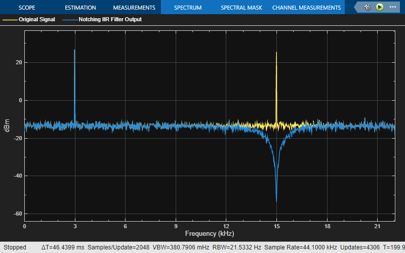
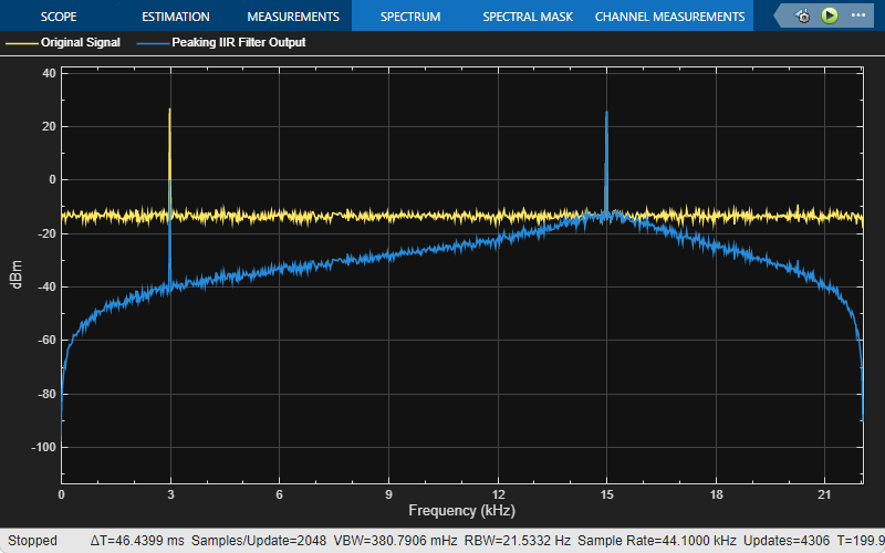
Pass the noisy sinusoidal signal through the notch-peak filter. Plot the input and notch-peak IIR filter output spectrum in the spectrum analyzer.
In the notch filter output, the tone at 3 kHz is attenuated as it coincides with the notch of the filter, while the tone at 15 kHz is unaffected. In the peak filter output, the tone at 3 kHz is unaffected as it coincides with the peak of the filter, while the tone at 15 kHz is attenuated.


Using the manual switch, change the center frequency of the notch-peak IIR filter to 15 kHz. The 15 kHz tone in the notch filter output is attenuated as it coincides with the new notch of the filter, while the tone at 3 kHz is unaffected. In the peak filter output, the tone at 15 kHz coincides with new peak of the filter, and therefore is unaffected, while the tone at 3 kHz is attenuated.

Since R2024a
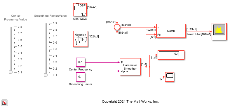
Vary the center frequency of the IIR notch filter. Smooth the center frequency value using the Parameter Smoother block. Note the smoothing behavior of the parameter in the Time Scope when you vary the smoothing factor.
Open the notchFilter_smoothingFactor.slx model. The input is a noisy sinusoidal signal with a frequency of 2 kHz, sample rate of 44.1 kHz, and contains 1024 samples per frame. Pass this signal through a Notch-Peak Filter block. The block outputs the Notch filter output and accepts the filter center frequency through the input port Fc. The Sample rate mode parameter of the block is set to Use normalized frequency (0 to 1). This setting enables the block to accept frequency specifications in normalized units.
Vary the center frequency of the notch between 0.1 and 0.8 using the slider. Smooth the variation of the center frequency using the Parameter Smoother block. When the smoothing factor is 0, no smoothing occurs and the parameter changes abruptly. As the smoothing factor approaches 1, smoothing increases and the parameter changes gradually.
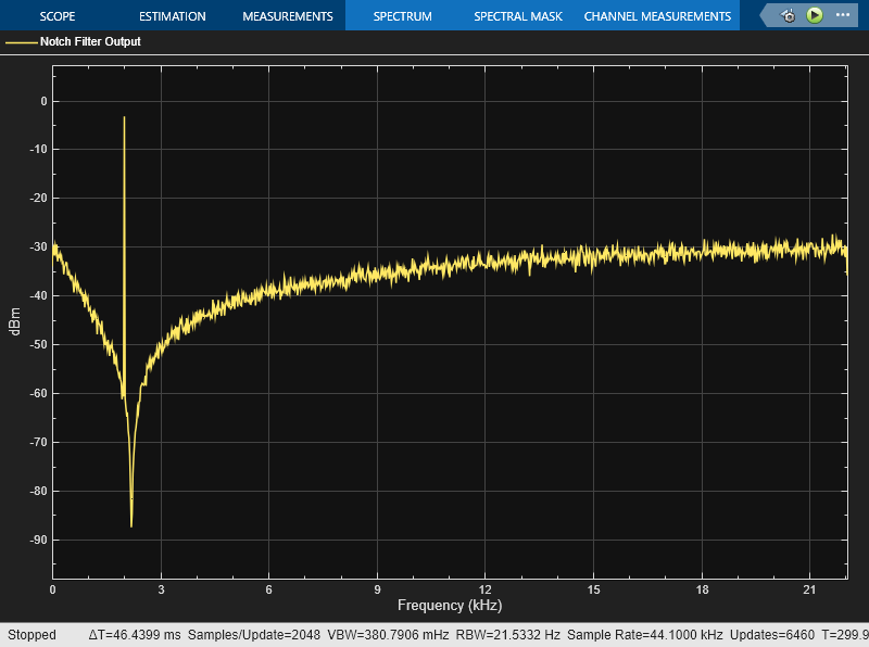
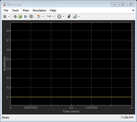
Run the model. The center frequency is 0.1. The frequency tone of the sinusoidal signal falls in the notch of the filter attenuating the signal.
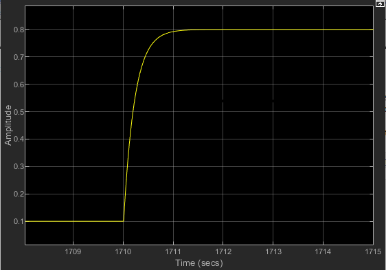
When you change the center frequency to 0.8, with a sample rate of 44.1 kHz, the center of the notch moves to 17.64 kHz and the tone is unaffected.

Vary the smoothing factor between 0.1 and 0.9 and notice the time it takes for the center frequency to change to the new value in each of these cases.
When alpha is 0.1, the parameter takes less than 0.1 seconds to change to its new value.

When alpha is 0.9, the parameter takes around 1 second to change to its new value. This is because a higher smoothing factor changes the parameter more gradually.
Ports
Input
Output
Parameters
Block Characteristics
Data Types |
|
Multidimensional Signals |
|
Variable-Size Signals |
|
Algorithms
The design equation for the peak filter is:
The design equation for the notch filter is:
with
where ω0 = 2πf0/fs is the center frequency in radians/sample (f0 is the center frequency in Hz and fs is the sampling frequency in Hz). Δω = 2πΔf/fs is the 3 dB bandwidth in radians/sample (Δf is the 3 dB bandwidth in Hz). Note that the two filters are complementary:
The filter is implemented as follows:

where
Notice that Gcf depends only on the center frequency, and G3dB depends only on the 3 dB bandwidth.
References
[1] Orfanidis, Sophocles J. Introduction to Signal Processing. Upper Saddle River, NJ: Prentice-Hall, 1996.