Simulate Vision and Radar Sensors in Unreal Engine Environment
This example shows how to implement a synthetic data simulation for tracking and sensor fusion in Simulink® with using the Unreal Engine® simulation environment from Epic Games®. It closely follows the Sensor Fusion Using Synthetic Radar and Vision Data in Simulink example.
Introduction
Automated Driving Toolbox™ provides tools for authoring, simulating, and visualizing virtual driving scenarios. With these scenarios, you can simulate rare and potentially dangerous events, generate synthetic radar and vision detections from the scenarios, and use the synthetic detections to test vehicle algorithms. This example covers the entire synthetic data workflow in Simulink using the 3D simulation environment.
Setup and Overview of Model
Prior to running this example, the roads, actors, and trajectories in the scenario were created using this procedure:
Extract the center locations from a portion of the road in the Define Road Layouts Programmatically 3D scene, using the techniques introduced in Select Waypoints for Unreal Engine Simulation.
Create a road in the Driving Scenario Designer that has these extracted locations as its road center values.
Define multiple moving vehicles on the road that have trajectories similar to the ones in the scenario defined in Sensor Fusion Using Synthetic Radar and Vision Data in Simulink.
Save the scenario file, curved_road.mat, from the Driving Scenario Designer and load them into the model using a Scenario Reader block.
Output poses of vehicles from the Scenario Reader block and convert them to the world coordinates. Use the Cuboid to 3D Simulation block to convert to X, Y, and Yaw required by the 3D vehicle block.
The actor poses provided by the Scenario Reader block is used by the Simulation 3D Vehicle with Ground Following blocks to define the locations of the ego vehicle, lead vehicle, and other vehicles at each time step of the simulation.
close;
if ismac
    error(['3D Simulation is supported only on Microsoft' char(174) ' Windows' char(174) ' and Linux' char(174) '.']);
end

open_system('SimulateSensorsIn3DEnvironmentModel');

Simulating Sensor Detections
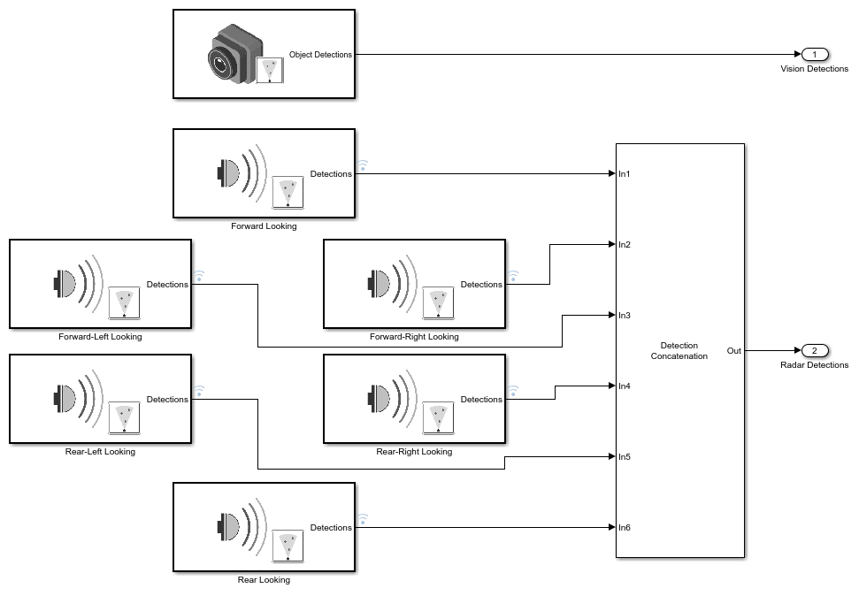
In this example, you simulate an ego vehicle that has a vision sensor on its front bumper and six radar sensors covering the full 360 degrees field of view. The ego vehicle is equipped with a long-range radar on both the front and rear of the vehicle. Each side of the vehicle has two short-range radars, each covering 90 degrees. One radar on each side covers from the middle of the vehicle to the back. The other radar on each side covers from the middle of the vehicle forward.
The Ego Sensors subsystem contains the one Simulation 3D Vision Detection Generator block and six Simulation 3D Probabilistic Radar blocks that model the previously described sensors. The outputs of the radar blocks are concatenated using a Detection Concatenation block. In the top-level model, the radar output is then concatenated with the vision output to create a single stream of detections to be fused by the Multi-Object Tracker block.
open_system('SimulateSensorsIn3DEnvironmentModel/Ego Sensors')
The probabilistic radars "see" not only an actor's physical dimensions (e.g., length, width, and height) but are also sensitive to an actor's electrical size. An actor's electrical size is referred to as its radar cross-section (RCS). The RCS patterns for the vehicles in the simulation are defined using the Simulation 3D Probabilistic Radar Configuration block.

Use this block to define the RCS patterns for all of the actors in the simulation. Any actors that do not have a specified RCS pattern use the default RCS value.
Tracking and Sensor Fusion
The detections generated by the ego vehicle's suite of radars are preprocessed using a helper Detection Clustering block before they are fused using the Multi-Object Tracker block. The multi-object tracker is configured with the same parameters used in the corresponding Simulink example, Sensor Fusion Using Synthetic Radar and Vision Data in Simulink. The output from the Multi-Object Tracker block is a list of confirmed tracks.
Display
The Bird's-Eye Scope is a model-level visualization tool in Simulink opened from the Simulink toolstrip. After opening the scope, click Find Signals to set up the signals. Then run the simulation to display the ego actor, radar and vision detections, and tracks. The following image shows the scope's display for this example.

When the simulation starts, a few seconds are needed to initialize the Unreal Engine simulation environment, especially when running it for the first time. Once this initialization is complete, the simulation environment opens in a separate window. The following image is a snapshot of the simulation window corresponding to the snapshot of the Bird's-Eye Scope shown in the previous image.

The simulated vehicles are shown in the simulation window. The detections and tracks generated by the simulation appear only in the Bird's-Eye Scope.
Summary
In this example, you learned how to extract road centers from a 3D scenario for use in the Driving Scenario Designer app. You also learned how to export the vehicle trajectories created from the road segments for use in the 3D simulation environment in Simulink. You then learned how to configure a probabilistic camera model and multiple probabilistic radar models in the Unreal Engine environment and how to fuse the detections from the multiple sensors located around the ego vehicle's perimeter using a multi-object tracker. The confirmed tracks generated by the tracker can then be used for control algorithms such as adaptive cruise control (ACC) or forward collision warning (FCW).
close_system('SimulateSensorsIn3DEnvironmentModel');
See Also
Apps
Blocks
- Simulation 3D Scene Configuration | Simulation 3D Vehicle with Ground Following | Simulation 3D Probabilistic Radar | Simulation 3D Probabilistic Radar Configuration | Detection Concatenation | Multi-Object Tracker