Integrate and Verify C++ Code of Sensor Fusion Algorithm in Simulink
This example shows how to integrate C++ code of a sensor fusion algorithm into Simulink®. You can also evaluate the performance of the integrated algorithm using the generalized optimal subpattern assignment (GOSPA) metric. For more information, see the Generalized Optimal Subpattern Assignment Metric (Sensor Fusion and Tracking Toolbox) block.
Introduction
The forward vehicle sensor fusion component of an automated driving system performs information fusion from different sensors to perceive the environment in front of an autonomous vehicle. This component is central to the decision-making process in various automated driving applications, such as highway lane following and forward collision warning. This example shows how to integrate and test a sensor fusion algorithm developed in C++ in an automated driving application. You integrate the C++ code of a sensor fusion algorithm into the Forward Vehicle Sensor Fusion test bench model using the C Function (Simulink) block, and verify the performance of the sensor fusion algorithm using the GOSPA metric. This example tests the C++ algorithm in a 3D simulation environment that uses the Unreal Engine® from Epic Games®. The Unreal Engine driving simulation environment requires a Windows® 64-bit platform.
if ~ispc
    error("3D simulation is supported only on Microsoft"+char(174)+" Windows"+char(174)+".")
end
In this example, you:
Explore C++ Code Interfaces — Explore C++ code of a sensor fusion algorithm and its interfaces.
Explore Test Bench Model — The test bench model contains modules for sensors and metrics assessment, and a C Function block to integrate the C++ code with these modules.
Simulate Test Bench and Evaluate Results — Simulate the model and compare the results of C++ code implementation with the
Forward Vehicle Sensor Fusionreference model using GOSPA metric.Explore Additional Scenarios — Test the system in other scenarios under additional conditions.
Explore C++ Code Interfaces
This example provides a file of C++ code, SensorFusionExample.cpp, consisting of a simple sensor fusion algorithm that accepts vision and radar detections and provides tracks of target vehicles relative to the ego vehicle. Due to the simplicity of the algorithm you can expect it to demonstrate less robust performance than the Forward Vehicle Sensor Fusion algorithm. The intent of the C++ algorithm is to showcase the integration of its inputs with the vision and radar sensor models and its output tracks with the metrics block in Simulink.
This example also provides the SensorFusionExampleHandler.hpp file, which contains functions to initialize, process, and terminate the C++ code of the sensor fusion algorithm.

SensorFusionInit— Initializes the data required by the algorithm.SensorFusion— Implements the algorithm that takes radar data, vision data, and time as input and outputs a list of tracks.SensorFusionTerminate— Clears the data used by algorithm.
Implementation of the handler functions present in SensorFusionExampleHandler.cpp.
The SensorFusionExampleInterfaces.hpp header file defines these code interfaces of the C++ algorithm.
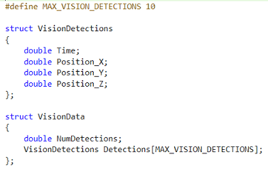
VisionData— Input structure that contains the timestamp and position information (x, y, z) of the object detected using camera data.
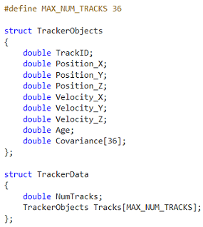
RadarData— Input structure that contains the timestamp, position (x, y, z), velocity (vx, vy, vz), and covariance information of the object detected using radar data.

Tracks— Output structure that contains the track ID, track position (x, y, z), velocity (vx, vy, vz), age, and covariance of each detected track.
To create bus objects for C++ structures, this example defines the Simulink.importExternalCTypes function inside the helperSLSensorFusionSetup helper function. The Simulink.importExternalCTypes function takes the header file as input, and automatically creates the bus objects for the VisionData, RadarData, and Tracks structures in the MATLAB® base workspace. For more information, see Simulink.importExternalCTypes (Simulink).
Explore Test Bench Model
This example modifies the test bench model from the Forward Vehicle Sensor Fusion example. To integrate C++ code of a sensor fusion algorithm, this example adds a C Function block to the test bench model.
To explore the test bench model, load the forward vehicle sensor fusion project and navigate to example directory.
openProject("FVSensorFusion");cd ..
Open the test bench model.
open_system("SensorFusionTestBench")

This test bench model contains these modules:
Sensors and Environment— Specifies the scene, vehicles, and sensors used for simulation.Pack Vision Detections— Packs data from the vision sensor into the format that the C++ code accepts.Pack Radar Detections— Packs data from the radar sensor into the format that the C++ code accepts.C++ Sensor Fusion— Calls the external C++ code of the sensor fusion algorithm, and integrates the code into the test bench model.Unpack Tracks— Unpacks the C++ code output into the required Simulink bus format.Forward Vehicle Sensor Fusion— Implements the radar clustering, detection concatenation, fusion, and tracking algorithms.Evaluate Tracker Metrics— Assesses the performance of the C++ code and FVSF algorithms, using the GOSPA metric.
The Sensors and Environment and Forward Vehicle Sensor Fusion are based on the subsystems used in the Forward Vehicle Sensor Fusion example. This example focuses on the Pack Vision Detections, Pack Radar Detections, Unpack Tracks, and C++ Sensor Fusion blocks, and the Evaluate Tracker Metrics subsystem.
Pack Vision Detections Block
The Pack Vision Detections block converts the vision sensor output into a format required by the C++ code as shown in this image.

The sensor output structure contains these fields:
Time— Time at which the object is detected.Measurement— Measurement of the form [ x; y; z; vx; vy; vz ], where (x, y, z) represents the coordinates for the position of the detected object and (vx, vy, vz) represents the velocity components of the detected object. These measurements are in the Cartesian coordinate system with respect to the sensor.
For more information about the vision sensor, see Simulation 3D Vision Detection Generator.
Pack Radar Detections Block
The Pack Radar Detections block converts the radar sensor output into a format required by the C++ code as shown in this image.
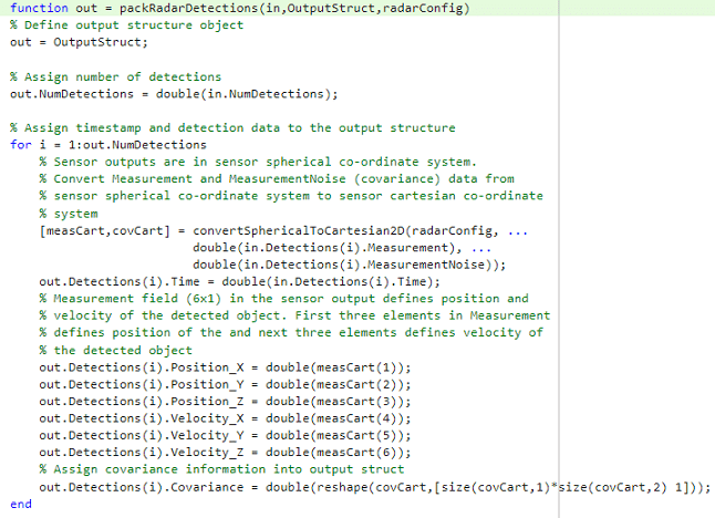
The sensor output structure contains these fields:
Time— Time at which the object is detected.Measurement— Position and velocity of the detected object in the Spherical coordinate system.MeasurementNoise— Measurement noise covariance matrix of the detected object in the Spherical coordinate system.
The Pack Radar Detections block uses the convertSphericalToCartesian2D function to convert detections from the Spherical to the Cartesian coordinate system.
For more information about the radar sensor, see Simulation 3D Probabilistic Radar.
Unpack Tracks Block
The Unpack Tracks block converts C++ code output data into a Simulink bus format, which contains these fields:
TrackID— ID of the track.State— Position and velocity of the track in the form [ x; vx; y; vy; z; vz ].Age— Number of times the track survived.Covariance— Uncertainty covariance matrix.

C++ Sensor Fusion Block
The C++ Sensor Fusion block is a C Function block that calls the external C++ code defined in the SensorFusionExampleHandler.hpp file, and integrates the code into the test bench model. For more information on the C Function block, see C Function (Simulink).
This example configures the C Function block to call the sensor fusion algorithm functions to initialize, process, and terminate the algorithm, as shown in this image.
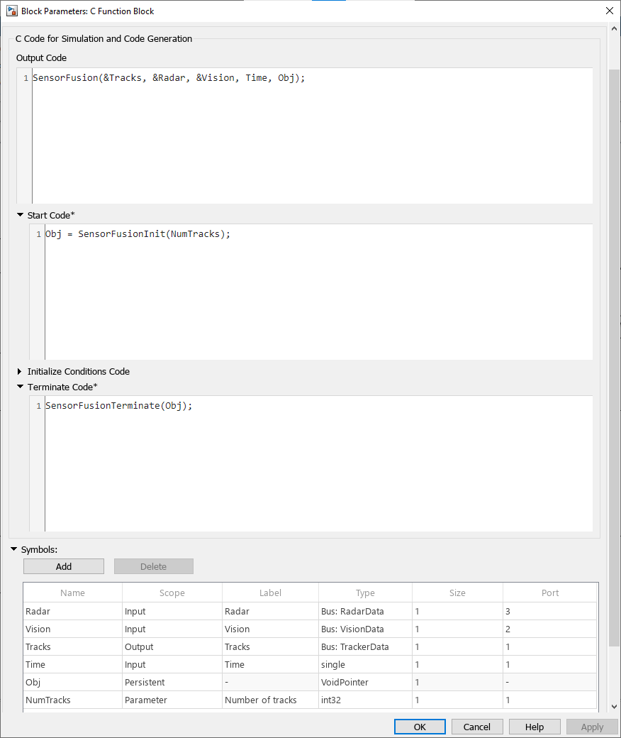
Configure the C Function block using these parameters:
Output Code — Calls the process function
SensorFusionat each simulation time step.Start Code — Calls the initialization code
SensorFusionInitonce at the start of simulation.Terminate Code — Calls the termination code
SensorFusionTerminateat the end of the simulation. The termination code frees up memory.Symbols — Defines the scope and type of variables required by the C++ algorithm.
Radar,Vision, andTimeare the inputs,Tracksis the output, andObjis a persistent variable that holds a class object of the C++ algorithm. TheNumTracksparameter specifies the maximum number of tracks.
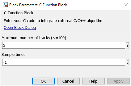
You can initialize the state variables of C++ sensor fusion algorithm using the C Function block. This example defines the maximum number of tracks variable using the Block Parameters dialog box, as shown in this image.
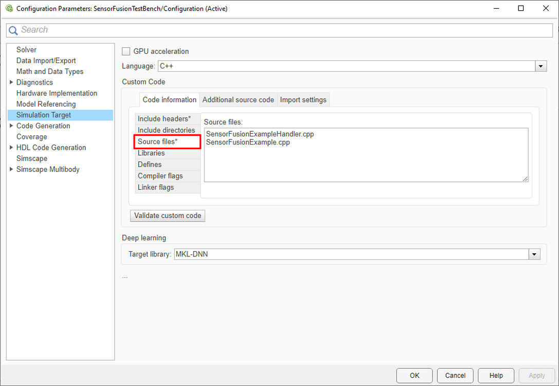
Use these steps to specify the filenames and dependencies of the C++ code for the sensor fusion algorithm:
1. On the Modeling tab of the Simulink toolstrip, select Model configuration parameters.

2. In the Configuration Parameters window, in the navigation pane, select Simulation Target.
3. Specify Language as C++.
4. In the Custom Code section, on the Code Information tab, select Include headers and enter the name of the header file, SensorFusionAlgorithmHandler.hpp, with the #include tag, in the Include headers box: #include "SensorFusionAlgorithmHandler.hpp".

5. Select Source files and, in the Source files box, enter the names of the source files, SensorFusionExampleHandler.cpp and SensorFusionExample.cpp.
Evaluate Tracker Metrics Subsystem
The Evaluate Tracker Metrics subsystem computes metrics using a Generalized Optimal Subpattern Assignment Metric block to assess the performance of the sensor fusion algorithm implemented using C++ code and compare it to the Forward Vehicle Sensor Fusion reference model.
open_system("SensorFusionTestBench/Evaluate Tracker Metrics")

To evaluate the performance, you must remove the actors that are outside the coverage area of the sensors from the ground truth information. For this purpose, the subsystem uses the Filter Within Coverage block to retain only those actors that are within the coverage area of the sensors.
The subsystem contains a Generalized Optimal Subpattern Assignment Metric block, which computes these metrics:
GOSPA metric — This metric measures the distance between a set of tracks and their ground truths, and combines both assignment and state-estimation accuracy into a single cost value.
Localization error — This error indicates the state-estimation accuracy. A high value indicates that the assigned tracks do not estimate the state of the truths correctly.
Missed target error — This error indicates the presence of missed targets. A high value indicates that targets are not being tracked.
False track error — This error indicates the presence of false tracks.
Simulate Test Bench and Evaluate Results
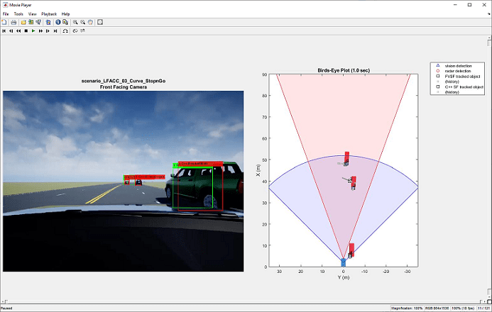
During simulation, you can visualize the scenario in both the 3D simulation window and using the bird's-eye scope.
To open the scope, on the Simulation tab of the Simulink toolstrip, in the Review Results section, select Bird's-Eye Scope. On the Bird's-Eye Scope toolstrip, click Find Signals to find the signals the scope can display. To update the displayed signals during and after simulation, click *Update Signals.
Configure the SensorFusionTestBench model to simulate the scenario_LFACC_03_Curve_StopnGo scenario. This scenario contains six vehicles, including the ego vehicle. The scenario function also defines their trajectories. In this scenario, the ego vehicle is in the same lane as a lead vehicle. In the lane to the right of the ego vehicle, target vehicles indicated in green and blue travel in the same direction as the ego and lead vehicles. In the lane to the left of the ego vehicle, target vehicles indicated in yellow and purple travel in the opposite direction as the ego vehicle.
helperSLSensorFusionSetup(scenarioFcnName="scenario_LFACC_03_Curve_StopnGo")
Simulate the test bench model.
sim("SensorFusionTestBench")
During the simulation, the model outputs the GOSPA metric and its components. The model logs the metrics, with the confirmed tracks and ground truth information, to the base workspace variable logsout. You can plot the values in logsout by using the helperPlotSensorFusionResults function.
helperPlotSensorFusionResults(logsout);

The plots show that the forward vehicle sensor fusion algorithm performs better than the sensor fusion algorithm implemented using C++ code. This is expected, because this example uses a simple C++ sensor fusion algorithm to focus on how to integrate C++ code into a test bench model.
During simulation, the model also records the output of the camera sensor to the forwardFacingCamera.mp4 file. You can use the helperPlotSFDetectionResults function to visualize the simulated detections and record the visualized detections to a video file to enable review by others who do not have access to MATLAB.
Plot the detection results from the logged data, generate a video, and open the Video Viewer app.
hVideoViewer = helperPlotSFDetectionResults(...
    logsout,"forwardFacingCamera.mp4",scenario,camera,radar, ...
    scenarioFcnName, ...
    RecordVideo=true, ...
    RecordVideoFileName=scenarioFcnName + "_VPA", ...
    OpenRecordedVideoInVideoViewer=true, ...
    VideoViewerJumpToTime=0);
Explore Other Scenarios
You can use the procedure in this example to explore these other scenarios, which are compatible with the SensorFusionTestBench model:
scenario_LFACC_01_Curve_DecelTargetscenario_LFACC_02_Curve_AutoRetargetscenario_LFACC_03_Curve_StopnGo(default)scenario_LFACC_04_Curve_CutInOutscenario_LFACC_05_Curve_CutInOut_TooClosescenario_LFACC_06_Straight_StopandGoLeadCarscenario_FVSF_01_Curve_FourVehiclesscenario_FVSF_02_Straight_FourVehiclesscenario_FVSF_03_Curve_SixVehicles
Use these additional scenarios to analyze the SensorFusionTestBench model under different conditions.
See Also
Blocks
- Simulation 3D Vision Detection Generator | Simulation 3D Probabilistic Radar | C Function (Simulink)
Topics
- Forward Vehicle Sensor Fusion
- Automate Testing for Forward Vehicle Sensor Fusion
- Automate Real-Time Testing for Forward Vehicle Sensor Fusion
- Automate PIL Testing for Forward Vehicle Sensor Fusion
- Automate Real-Time Testing of Highway Lane Following Controller Using ASAM XIL
- Generate C++ Message Interfaces for Lane Following Controls and Sensor Fusion
- Highway Lane Following