Generate Code for Highway Lane Change Planner
This example shows how to design, test, and generate C++ code for a lane change planner for highway driving. This example closely follows the Highway Trajectory Planning Using Frenet Reference Path example. In this example, you:
Design the test bench model to verify the functionality of the highway lane change planner using ground truth information.
Generate code for a highway lane change planner, profile the execution time, and validate the functional equivalence with simulation.
Introduction
The highway lane change system enables the ego vehicle to automatically move from one lane to another lane on a highway. The highway lane change planner is a fundamental component of a highway lane change system. It is expected to handle different driving behaviors to safely navigate the ego vehicle from one point to another point. In this example, the highway lane change planner samples trajectories for different driving behaviors such as cruise control, lead car following (LCF), and lane change maneuvers. It then evaluates the cost, feasibility, and possibility of collision with other vehicles and generates an optimal collision-free trajectory. This example also shows how to generate C++ code and verify the generated code using software-in-the-loop (SIL) execution. In this example, you:
Explore test bench model — The test bench model contains the scenario and environment, planner configuration parameters, highway lane change planner, and metrics to assess the functionality.
Model lane change planner — The reference model contains a terminal state sampler, motion planner, and motion prediction module. The terminal state sampler samples terminal states based on the planner parameters and the current state of both the ego vehicle and other vehicles in the scenario. The motion prediction module predicts the future motion of most important objects (MIOs). Motion planner samples trajectories and outputs an optimal trajectory.
Simulate with cruise control and lead car following — Simulate the system by enabling only cruise control and lead car following maneuvers.
Simulate with lane change — Simulate the system by adding a lane-change maneuver.
Generate C++ code — Configure the lane change planner reference model to run in SIL mode, and verify the functional equivalence with simulation.
Assess execution time and perform code coverage analysis — Assess the performance of the generated code by using the execution time and coverage.
Explore other scenarios — These scenarios test the system under additional conditions. You can apply the modeling patterns used in this example to test your own planner component for the highway lane change system.
Explore Test Bench Model
The highway lane change planner system in this example contains a highway lane change planner test bench and a reference model.
Test bench model — The test bench model simulates and tests the behavior of the highway lane change planner algorithm in a closed loop.
Reference model — The Highway Lane Change Planner reference model implements the highway lane change planner algorithm and generates C++ code of the algorithm.
The reference model can be integrated with the Highway Lane Change system. To explore the test bench model, load the highway lane change planner project.
openProject("HLCPlanner");
Open the test bench model.
open_system('HighwayLaneChangePlannerTestBench');

Opening this model runs the helperSLHighwayLaneChangePlannerSetup script, which initializes the road scenario using a drivingScenario object in the base workspace. It also configures the planner parameters, initial ego vehicle information, lane information, global plan points required by the planner, and Simulink bus signals required for defining the inputs and outputs for the HighwayLaneChangePlannerTestBench model. The test bench model contains these subsystems:
Scenario and Environment — Subsystem that specifies the scene, vehicles, and map data used for simulation.
Planner Configuration Parameters — Subsystem that specifies the configuration parameters required for the planner algorithm.
Highway Lane Change Planner — Subsystem that implements the lane change planner algorithm for the highway.
Metrics Assessment — Subsystem that specifies metrics to assess the highway lane change planner behavior.
Visualization — Subsystem that visualizes the status of the ego vehicle and other vehicles defined in the scenario.
Pack Actor — Subsystem that updates the actor bus using the current state of the ego vehicle from the planner.
The Scenario and Environment subsystem uses the Scenario Reader block to provide road network and vehicle ground truth positions and map data required for the highway lane change planner algorithm. This subsystem outputs the map data required by the lane change planner. Open the Scenario and Environment subsystem.
open_system('HighwayLaneChangePlannerTestBench/Scenario and Environment');
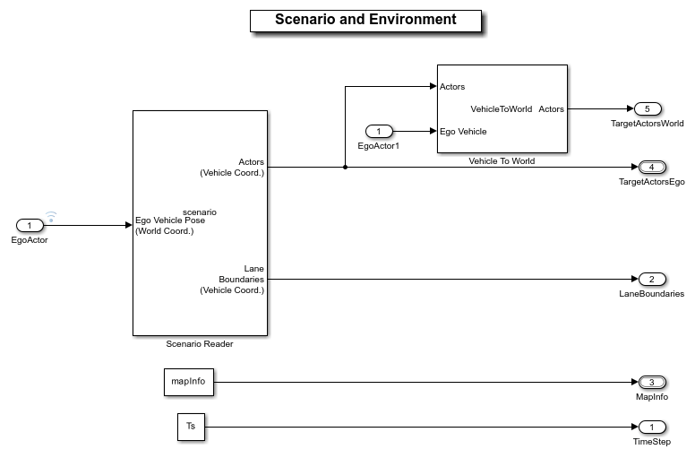
The Scenario Reader block is configured to read the drivingScenario object from the base workspace. It uses this object to read the actor data and lane boundary information. It takes in ego vehicle information to perform a closed loop simulation. This block outputs ground truth vehicle information from the actors in ego vehicle coordinates. The Vehicle To World block is used to convert target vehicle positions from vehicle coordinates to world coordinates. This subsystem reads map data from the base workspace and outputs information about lanes and the reference path.
The Planner Configuration Parameters subsystem reads base workspace variables using constant blocks and constructs a bus structure using the Bus Creator block. The bus created by this subsystem is used by the lane change planner.
open_system("HighwayLaneChangePlannerTestBench/Planner Configuration Parameters");
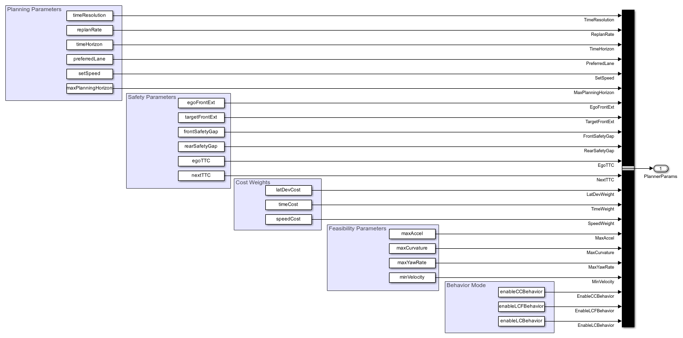
The Planner Configuration Parameters block reads the following parameters from the base workspace:
timeResolutiondefines the time resolution of the sampled trajectories in seconds.replanRatedefines the replan rate for the planner in seconds.timeHorizondefines a vector of time horizons for sampling the trajectories in seconds.preferredLanedefines the preferred lane for the ego vehiclesetSpeeddefines the driver set speed that ego vehicle can follow in m/s.maxPlanningHorizondefines the maximum longitudinal planning horizon in meters.egoFrontExtandtargetFrontExtdefine the front extension for the ego and target vehicles, respectively, in meters. These parameters are used to inflate the ego and target vehicles during collision checking.frontSafetyGapandrearSafetyGapdefine the safety gap between the ego vehicle and other vehicles.egoTTCandnextTTCdefine the time-to-collision bounds with other vehicles in the scenario.latDevCost,timeCost, andspeedCostdefine the weights for calculating the cost of sampled terminal states.maxAccel,maxCurvature,maxYawRate, andmaxVelocitydefine the kinematic feasibility bounds.enableCCBehavior,enableLCFBehavior, andenableLCBehaviorare used for enabling the sampling of terminal states for cruise control behavior, lead car following behavior (LCF), and lane change behavior, respectively.
The Pack Actor subsystem packs the information generated by the planner into the actor bus. The actor bus is used to update the ego actor information for the scenario reader block to perform closed loop simulation.
open_system('HighwayLaneChangePlannerTestBench/Pack Actor');
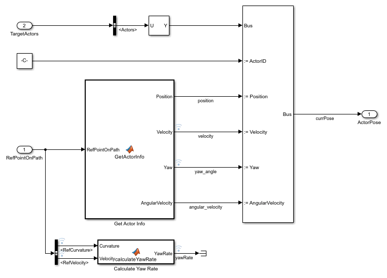
The Get Actor Info MATLAB® function block outputs actor information in the format required by the bus assignment block. The bus assignment block outputs the actor bus with updated information. The Calculate Yaw Rate MATLAB function block computes the yaw rate for the ego vehicle.
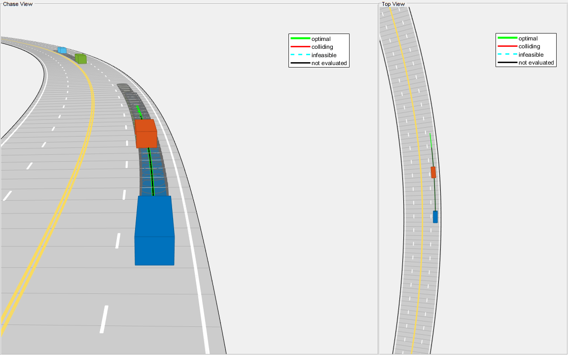
The Visualization block creates a MATLAB figure that shows the chase view and top view of the scenario and plots the ego vehicle, sampled trajectories, capsule list, and other vehicles in the scenario.
The Metrics Assessment subsystem assesses the highway lane change planner behavior using metrics that include the longitudinal and lateral jerk, collision, and time to collision. For more details, see Highway Lane Change.
Model Highway Lane Change Planner
The Highway Lane Change Planner reference model implements the main algorithm for the highway lane change system. The reference model reads map data, actor poses (in world coordinates), and planner parameters from Scenario and Environment subsystem to perform trajectory planning. The model uses the Fernet coordinate system to find the most important MIOs surrounding the ego vehicle. Subsequently, the model samples terminal states for different behaviors, predicts the motion of target actors, and generates multiple trajectories. Finally, the model evaluates the costs of generated trajectories and checks for the possibility of collision and kinematic feasibility to estimate the optimal trajectory. Open the Highway Lane Change Planner reference model.
open_system('HighwayLaneChangePlanner');
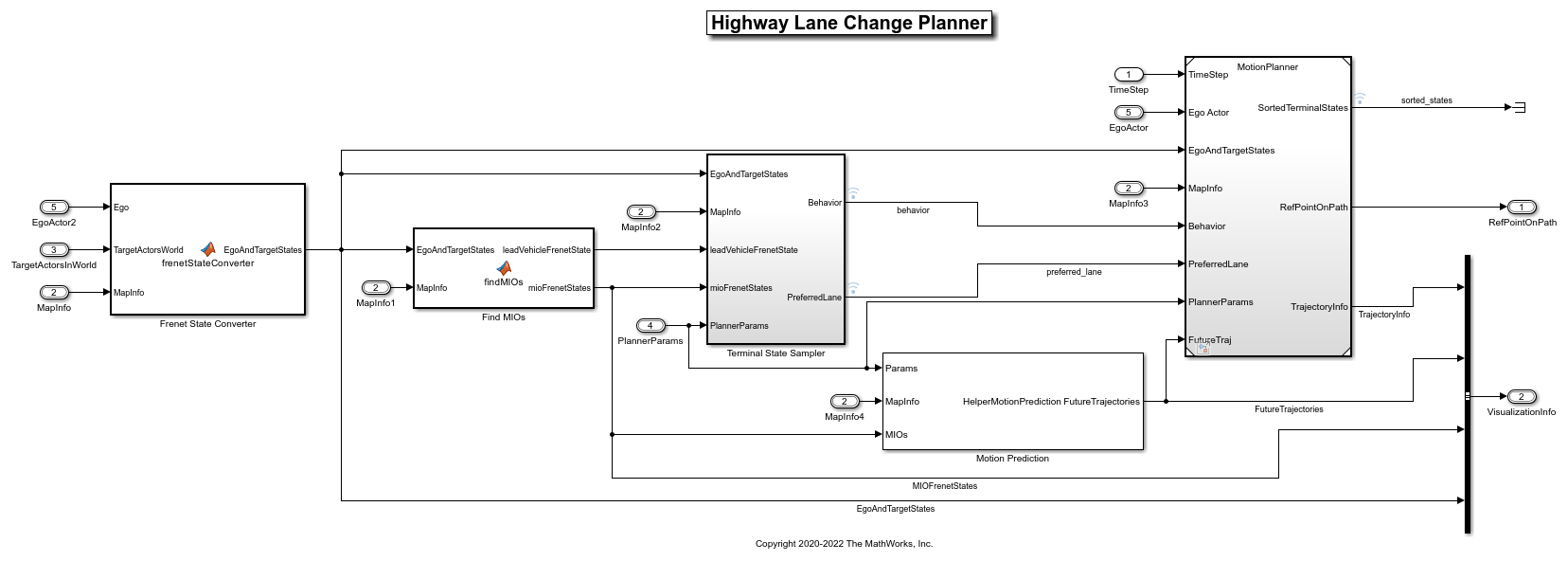
The Highway Lane Change Planner reference model contains the following blocks:
The Frenet State Converter MATLAB function block converts the ego and target actor information into the Frenet coordinate system from the world coordinate system.
The Find MIOs MATLAB function block identifies the MIOs using ground truth vehicle poses with respect to the current state of the ego vehicle. The vehicles present in the front or rear of the ego vehicle are considered MIOs. The MIOs can also be present in adjacent lanes, as shown in the following figure.
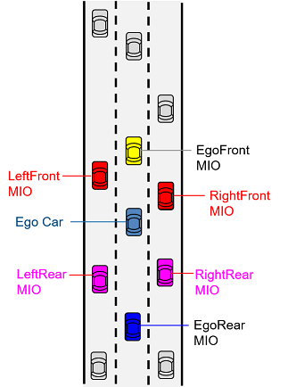
The Find MIOs block outputs information on the MIOs, including the lead vehicle, in the Frenet coordinate system.
Terminal State Sampler subsystem samples terminal states for cruise control, lead car following, and lane change behaviors. It outputs concatenated terminal states for the trajectory generator.
The Motion Prediction MATLAB system block predicts the motion of MIOs using a constant velocity model. The predicted states of the MIOs are used for collision checking. This block uses the
HelperMotionPredictionsystem object, which implements the constant velocity based motion prediction model. You can implement your own motion prediction module and test the test bench model.The Motion Planner reference model uses the predicted states of MIOs, planner parameters, and terminal states generated by the Terminal State Sampler to perform trajectory planning for the ego vehicle.
The Terminal State Sampler subsystem configures planner behavior by computing the terminal states using the ego vehicle and MIOs state information. Open the Terminal State Sampler subsystem.
open_system('HighwayLaneChangePlanner/Terminal State Sampler')
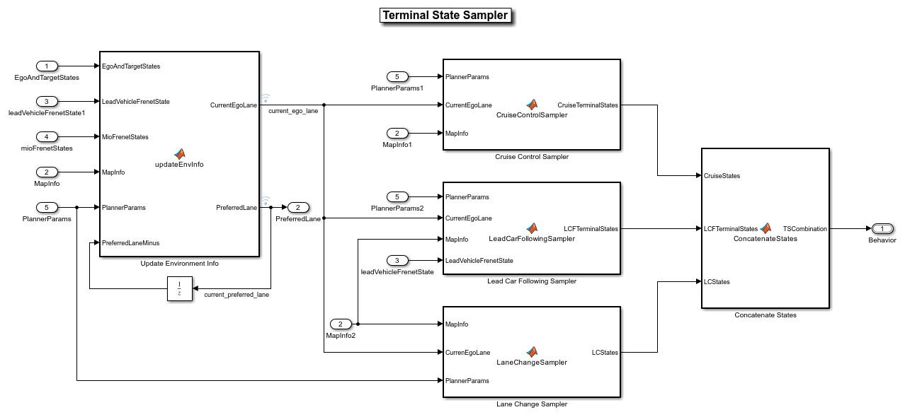
The Terminal State Sampler subsystem contains the following blocks:
Update Environment Info updates the current lane and the preferred lane for the ego vehicle based on its current pose. This block invokes the
updateEnvironmentInfofunction implemented in theHelperTerminalStateSamplerfunction, which is attached to this example.Cruise Control Sampler samples terminal states for the cruise behavior based on the current state of the ego vehicle. This block invokes the
cruiseControlSamplerfunction fromHelperTerminalStateSampler.Lead Car Following Sampler samples terminal states for adaptively changing the velocity of the ego vehicle with respect to the lead vehicle in the current ego lane. This block invokes the
leadCarFollowingSamplerfunction fromHelperTerminalStateSampler.Lane Change Sampler samples terminal states for lane change behavior for the ego vehicle. This block invokes the
laneChangeSamplerfunction fromHelperTerminalStateSampler.Concatenate States concatenates the terminal states from the Cruise Control Sampler, Lead Car Following Sampler, and Lane Change Sampler blocks.
You can design your own Terminal State Sampler to sample terminal states for other behaviors, such as stop and go. You can also enable or disable samplers in the Terminal State Sampler by using the flags defined in the helperSLHighwayLaneChangePlannerSetup script.
The Motion Planner reference model generates trajectories based on the sampled terminal states and planner parameters. Open the Motion Planner reference model.
open_system('MotionPlanner')
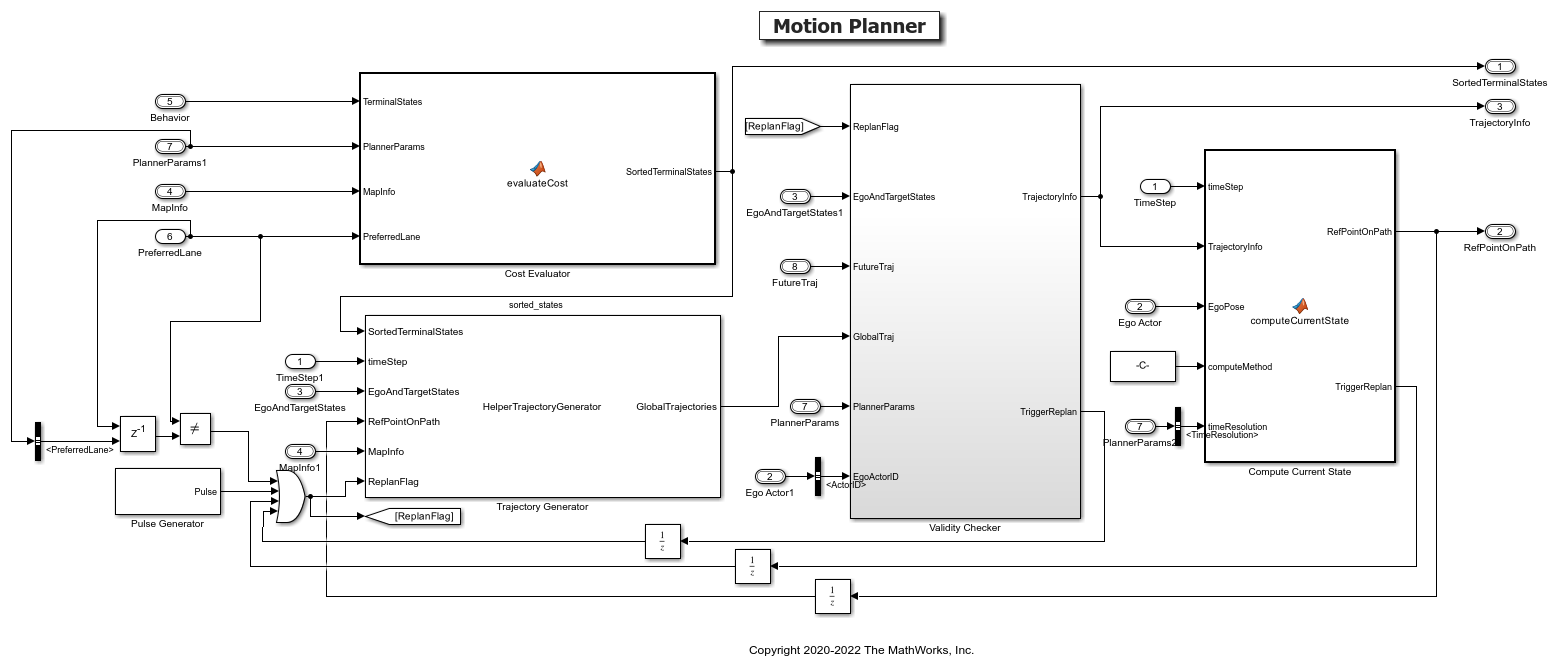
The Motion Planner reference model contains the following blocks:
The Pulse Generator block defines a replan period for the Trajectory Generator block. The default value is 1 second.
The Cost Evaluator block calculates the cost associated with all the sampled terminal states and sorts them in ascending order.
The Trajectory Generator block generates trajectories for the sampled terminal states. The sampled trajectories are in world coordinates.
The Validity Checker subsystem validates trajectories generated by the Trajectory Generator for feasibility and collision. It outputs the optimal trajectory that the ego car can follow.
The State Estimator block identifies the appropriate point on the path to follow. The generated path must conform to the road shape.
The Validity Checker subsystem checks for kinematic feasibility and collision of generated trajectories with predicted trajectories of MIOs. Open the Validity Checker subsystem.
open_system('MotionPlanner/Validity Checker')

The Kinematic Feasibility block uses the helperKinematicFeasibility function to check the feasibility of the yaw rate, curvature, acceleration, and velocity bounds for the generated trajectories. You can add other feasibility criteria for validating the trajectories.
The Collision Checker block checks for collision with future trajectories of MIOs. It outputs the optimal trajectory that the ego vehicle can follow. You can apply this modeling pattern and implement your own logic to evaluate the cost and feasibility to find the optimal trajectory.
The Highway Lane Change Planner test bench by default samples trajectories for cruise control, lead car following, and lane change behaviors. You can enable or disable these behaviors by setting the flags in the helperSLHighwayLaneChangePlannerSetup script.
Simulate with Cruise Control and Lead Car Following Behaviors
Set up the Highway Lane Change Planner test bench with cruise control and lead car following behavior and run the model to visualize the behavior of the system. Configure the test bench model to use the scenario_LC_15_StopnGo_Curved scenario. This scenario contains a slow moving lead vehicle in front of the ego vehicle. The lead car following behavior enables the ego vehicle to adjust its velocity to avoid collision with the slow moving lead vehicle. When you enable only cruise control behavior, the ego vehicle travels at the set velocity and avoiding collision with the lead vehicle is not possible.
helperSLHighwayLaneChangePlannerSetup("scenarioFcnName","scenario_LC_15_StopnGo_Curved");
By default, the helperSLHighwayLaneChangeSetup script configures the model by enabling the cruise control, lead car following, and lane change behaviors. Disable the lane change behavior and simulate the model to observe the system behavior.
enableLCBehavior = 0;
sim('HighwayLaneChangePlannerTestBench');
Close the figure.
hLCPlot = findobj( 'Type', 'Figure', 'Name', 'Lane Change Status Plot');
if ~isempty(hLCPlot)
    close(hLCPlot);
end
Plot the ego velocity and orientation to analyze the behavior of the ego vehicle during the simulation.
hPlotSimResults = helperPlotEgoLateralandLongitudinalResults(logsout);
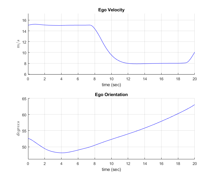
Observe that the ego vehicle negotiates with the lead vehicle by reducing its velocity to avoid collision. The change in the orientation of the ego vehicle is due to the fact that the vehicle is traveling along a curved road.
Close the figure.
close(hPlotSimResults);
Now, simulate the model by enabling lane change behavior.
Simulate and Visualize Lane Change Behavior
Now, enable the lane change behavior and simulate the model to observe the system behavior. Enabling the lane change behavior allows the ego vehicle to perform a lane change for maintaining the desired velocity and to avoid collision with the slow moving lead vehicle in the scenario.
enableLCBehavior = 1;
sim('HighwayLaneChangePlannerTestBench');
Close the figure.
hLCPlot = findobj( 'Type', 'Figure', 'Name', 'Lane Change Status Plot');
if ~isempty(hLCPlot)
    close(hLCPlot);
end
Plot the ego velocity and orientation to analyze the behavior of the ego vehicle during the simulation.
hPlotSimResults = helperPlotEgoLateralandLongitudinalResults(logsout);
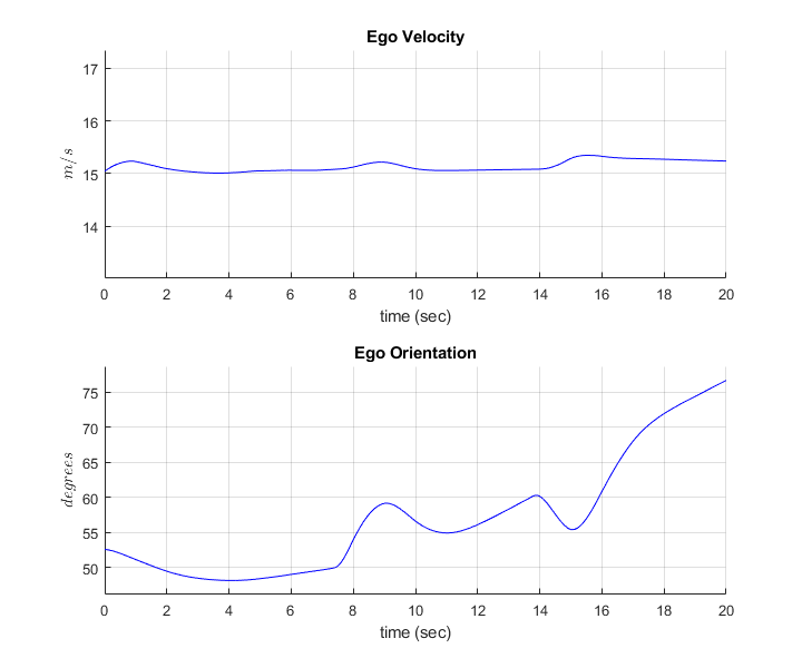
Observe that the ego vehicle maintains a nearly constant velocity and yet avoids collision with the slow moving lead car due to a lane change maneuver. The ego orientation plot clearly reflects the change in the ego orientation during the lane change.
Close the figure.
close(hPlotSimResults);
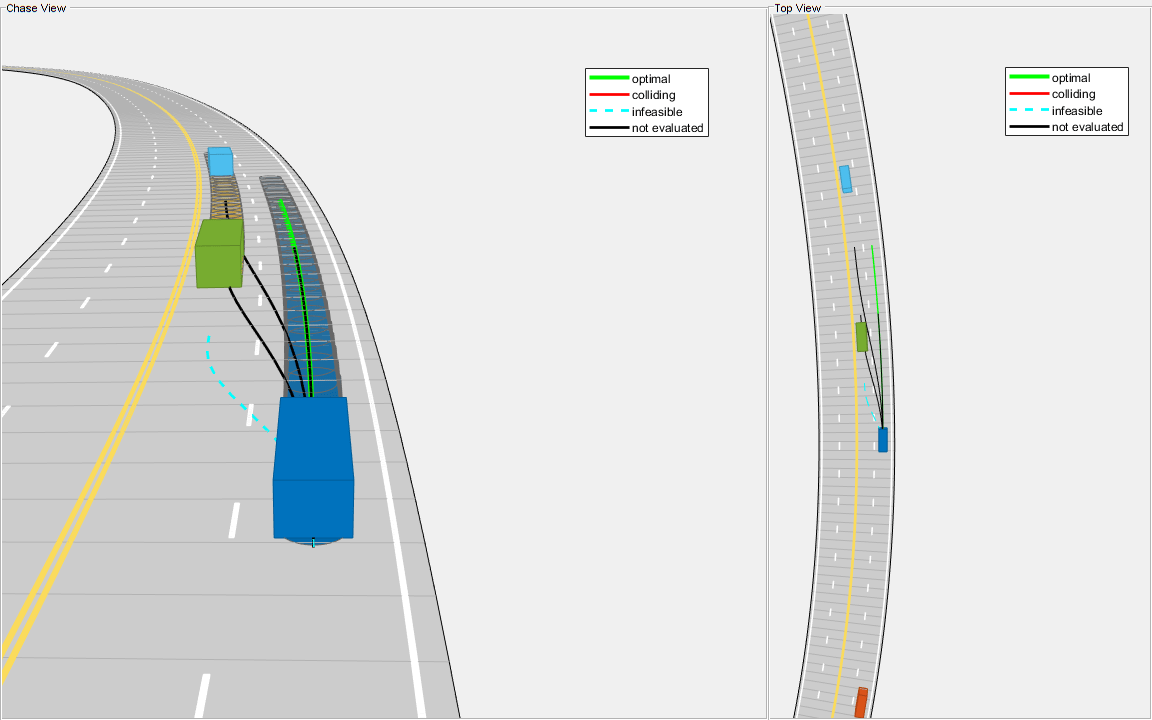
During the simulation, the model logs signals to base workspace as logsout. You can analyze the simulation results and debug any failures in the system behavior using the HelperAnalyzeLCPlannerSimulationResults class. The visualizeSimulationData method the class creates a MATLAB figure and plots chase view of the scenario. The slider in the figure enables you to select a desired simulation step to analyze different parameters shown in these panes:
Chase View — Shows chase view of the scenario showing ego vehicle, sampled trajectories, capsule list, and other vehicles.
Trajectory Information — Shows different attributes of sampled trajectories. The highlighted rows show the type of sampled trajectory by using the same color coding as shown in the Chase View.
MIO Information — Shows different attributes of identified MIOs. The color of the row matches the face color of the corresponding vehicle.
Mode — Shows the selected behavior for the ego vehicle.
Ego Velocity — Shows the velocity of ego vehicle. Units are in meters per second.
Simulation Step — Shows the simulation step number set using the slider.
Simulation Time — Shows time corresponding to simulation step. Units are in seconds.
Ego State — Shows parameters of the ego vehicle and identified lead vehicle.
Planner Parameters — Shows configuration parameters for the planner.
Run the script and explore the plot.
visualizatonObj = HelperAnalyzeLCPlannerSimulationResults(logsout);
visualizatonObj.visualizeSimulationData()

Generate C++ Code
You can now generate C++ code for the algorithm, apply common optimizations, and generate a report to facilitate exploring the generated code.
Configure the Highway Lane Change Planner and Motion Planner models to generate C++ code for real-time implementation of the algorithm. Set the model parameters to enable code generation and display the configuration values.
Now, set and view the model parameters to enable C++ code generation. Close the reference models to preserve the model on the root level before saving the model.
close_system('MotionPlanner');
helperSetModelParametersForCodeGeneration('MotionPlanner');
save_system('MotionPlanner');
close_system('HighwayLaneChangePlanner');
helperSetModelParametersForCodeGeneration('HighwayLaneChangePlanner');
save_system('HighwayLaneChangePlanner');
 Model  configuration parameters:

                 Parameter                      Value                                                              Description
    ___________________________________    _______________    ______________________________________________________________________________________________________________________

    {'SystemTargetFile'               }    {'ert.tlc'    }    {'Code Generation>System target file'                                                                                }
    {'TargetLang'                     }    {'C++'        }    {'Code Generation>Language'                                                                                          }
    {'SolverType'                     }    {'Fixed-step' }    {'Solver>Type'                                                                                                       }
    {'FixedStep'                      }    {'auto'       }    {'Solver>Fixed-step size (fundamental sample time)'                                                                  }
    {'EnableMultiTasking'             }    {'on'         }    {'Solver>Treat each discrete rate as a separate task'                                                                }
    {'ProdLongLongMode'               }    {'on'         }    {'Hardware Implementation>Support long long'                                                                         }
    {'BlockReduction'                 }    {'on'         }    {'Simulation Target>Block reduction'                                                                                 }
    {'MATLABDynamicMemAlloc'          }    {'on'         }    {'Simulation Target>Simulation Target>Dynamic memory allocation in MATLAB functions'                                 }
    {'OptimizeBlockIOStorage'         }    {'on'         }    {'Simulation Target>Signal storage reuse'                                                                            }
    {'InlineInvariantSignals'         }    {'on'         }    {'Simulation Target>Inline invariant signals'                                                                        }
    {'BuildConfiguration'             }    {'Faster Runs'}    {'Code Generation>Build configuration'                                                                               }
    {'RTWVerbose'                     }    {'off'        }    {'Code Generation>Verbose build'                                                                                     }
    {'CombineSignalStateStructs'      }    {'on'         }    {'Code Generation>Interface>Combine signal/state structures'                                                         }
    {'SupportVariableSizeSignals'     }    {'on'         }    {'Code Generation>Interface>Support variable-size signals'                                                           }
    {'CodeInterfacePackaging'         }    {'C++ class'  }    {'Code Generation>Interface>Code interface packaging'                                                                }
    {'GenerateExternalIOAccessMethods'}    {'Method'     }    {'Code Generation>Interface>Data Member Visibility>External I/O access'                                              }
    {'EfficientFloat2IntCast'         }    {'on'         }    {'Code Generation>Optimization>Remove code from floating-point to integer conversions that wraps out-of-range values'}
    {'ZeroExternalMemoryAtStartup'    }    {'off'        }    {'Code Generation>Optimization>Remove root level I/O zero initialization (inverse logic)'                            }
    {'CustomSymbolStrGlobalVar'       }    {'$N$M'       }    {'Code Generation>Symbols>Global variables'                                                                          }
    {'CustomSymbolStrType'            }    {'$N$M_T'     }    {'Code Generation>Symbols>Global types'                                                                              }
    {'CustomSymbolStrField'           }    {'$N$M'       }    {'Code Generation>Symbols>Field name of global types'                                                                }
    {'CustomSymbolStrFcn'             }    {'APV_$N$M$F' }    {'Code Generation>Symbols>Subsystem methods'                                                                         }
    {'CustomSymbolStrTmpVar'          }    {'$N$M'       }    {'Code Generation>Symbols>Local temporary variables'                                                                 }
    {'CustomSymbolStrMacro'           }    {'$N$M'       }    {'Code Generation>Symbols>Constant macros'                                                                           }
Generate code and review the code generation report for the reference model.
slbuild('HighwayLaneChangePlanner');
### Searching for referenced models in model 'HighwayLaneChangePlanner'.
### Found 1 model reference targets to update.
### Starting serial model reference code generation build.
### Starting build procedure for: MotionPlanner
### Successful completion of build procedure for: MotionPlanner
### Starting build procedure for: HighwayLaneChangePlanner
### Successful completion of build procedure for: HighwayLaneChangePlanner

Build Summary

Model reference code generation targets:

Model          Build Reason                               Status
========================================================================================
MotionPlanner  Target (MotionPlanner.cpp) did not exist.  Code generated and compiled.

Top model targets:

Model                     Build Reason                                         Status
=============================================================================================================
HighwayLaneChangePlanner  Information cache folder or artifacts were missing.  Code generated and compiled.

2 of 2 models built (0 models already up to date)
Build duration: 0h 7m 4.5761s
Use the code generation report to explore the generated code. To learn more about the code generation report, see Reports for Code Generation (Embedded Coder). Use the code interface report link in the code generation report to explore these generated methods:
initialize— Call once on initialization.step— Call periodically every step to execute the lane marker detection algorithm.terminate— Call once on termination.
Additional get and set methods for signal interface are declared in HighwayLaneChangePlanner.h and defined in HighwayLaneChangePlanner.cpp.
Assess Functionality of Code
After generating C++ code for the highway lane change planner, you can now assess the code functionality using software-in-the-loop (SIL) simulation. It provides early insight into the behavior of a deployed application. To learn more about SIL simulation, see SIL and PIL Simulations (Embedded Coder).
SIL simulation enables you to verify that the compiled generated code on the host is functionally equivalent to the normal mode.
Configure the algorithm and test bench model parameters to support SIL simulation and log execution profiling information.
helperSetModelParametersForSIL('HighwayLaneChangePlanner');
helperSetModelParametersForSIL('HighwayLaneChangePlannerTestBench');
HighwayLaneChangePlanner configuration parameters:

               Parameter                       Value                                    Description
    ________________________________    ____________________    ____________________________________________________________

    {'SystemTargetFile'            }    {'ert.tlc'         }    {'Code Generation>System target file'                      }
    {'TargetLang'                  }    {'C++'             }    {'Code Generation>Language'                                }
    {'CodeExecutionProfiling'      }    {'on'              }    {'Code Generation>Verification>Measure task execution time'}
    {'CodeProfilingSaveOptions'    }    {'AllData'         }    {'Code Generation>Verification>Save options'               }
    {'CodeExecutionProfileVariable'}    {'executionProfile'}    {'Code Generation>Verification>Workspace variable'         }


HighwayLaneChangePlannerTestBench configuration parameters:

               Parameter                       Value                                    Description
    ________________________________    ____________________    ____________________________________________________________

    {'SystemTargetFile'            }    {'ert.tlc'         }    {'Code Generation>System target file'                      }
    {'TargetLang'                  }    {'C++'             }    {'Code Generation>Language'                                }
    {'CodeExecutionProfiling'      }    {'on'              }    {'Code Generation>Verification>Measure task execution time'}
    {'CodeProfilingSaveOptions'    }    {'AllData'         }    {'Code Generation>Verification>Save options'               }
    {'CodeExecutionProfileVariable'}    {'executionProfile'}    {'Code Generation>Verification>Workspace variable'         }
Configure the test bench model to simulate in SIL mode.
set_param('HighwayLaneChangePlannerTestBench/Highway Lane Change Planner','SimulationMode','Software-in-the-loop (SIL)');
sim('HighwayLaneChangePlannerTestBench');
### Searching for referenced models in model 'HighwayLaneChangePlannerTestBench'.
### Found 2 model reference targets to update.
### Starting serial model reference code generation build.
### Starting build procedure for: MotionPlanner
### Successful completion of build procedure for: MotionPlanner
### Starting build procedure for: HighwayLaneChangePlanner
### Successful completion of build procedure for: HighwayLaneChangePlanner

Build Summary

Model reference code generation targets:

Model                     Build Reason                                          Status
==============================================================================================================
MotionPlanner             Code instrumentation settings changed.                Code compiled.
HighwayLaneChangePlanner  Target (HighwayLaneChangePlanner.cpp) did not exist.  Code generated and compiled.

2 of 2 models built (0 models already up to date)
Build duration: 0h 3m 47.686s
### Preparing to start SIL simulation ...
Building with 'Microsoft Visual C++ 2019 (C)'.
MEX completed successfully.
### Starting SIL simulation for component: HighwayLaneChangePlanner
### Application stopped
### Stopping SIL simulation for component: HighwayLaneChangePlanner

Close the figure.
hLCPlot = findobj( 'Type', 'Figure', 'Name', 'Lane Change Status Plot');
if ~isempty(hLCPlot)
    close(hLCPlot);
end
You can compare the outputs from normal simulation mode and SIL simulation mode. You can verify if the differences between these runs are within the tolerance limits by using the following code. Plot the differences of the detected lane boundary parameters between the normal simulation mode and SIL simulation mode.
runIDs = Simulink.sdi.getAllRunIDs;
normalSimRunID = runIDs(end - 1);
SilSimRunID = runIDs(end);
diffResult = Simulink.sdi.compareRuns(normalSimRunID ,SilSimRunID);
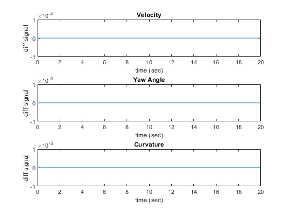
Plot the differences between the lane boundary parameters computed from normal mode and SIL mode.
hFigDiffResult = helperPlotLCPlannerDiffSignals(diffResult);

Close the figure handle.
close(hFigDiffResult);
Notice that the differences between normal mode of simulation and SIL mode of simulation are approximately zero.
Assess Execution Time and Coverage of Code
During the SIL simulation, log the execution time metrics for the generated code on the host computer to the variable executionProfile in the MATLAB base workspace. These times can be an early indicator of the performance of the generated code. For accurate execution time measurements, profile the generated code when it is integrated into the external environment or when you use processor-in-the-loop (PIL) simulation. To learn more about PIL profiling, refer to Create Execution-Time Profile for Generated Code (Embedded Coder).
Plot the execution time taken for the step function of HighwayLaneChangePlanner using the helperPlotLCPlannerExecutionProfile function.
hFigLCExeProfile = helperPlotLCPlannerExecutionProfile(executionProfile);
You can deduce the average time taken per frame for the highway lane change planner from this plot. For more information on generating execution profiles and analyzing them during SIL simulation, see Execution Time Profiling for SIL and PIL (Embedded Coder).
Close the figure.
close(hFigLCExeProfile);
If you have a Simulink Coverage™ license, you can also perform the code coverage analysis for the generated code to measure the testing completeness. You can use missing coverage data to find gaps in testing, missing requirements, or unintended functionality. Configure the coverage settings and simulate the test bench model to generate the coverage analysis report. Find the generated report CoverageResults/HighwayLaneChangePlanner_modelrefsil_summary_cov.html in the working directory.
if(license('test','Simulink_Coverage'))
    helperCoverageSettings('HighwayLaneChangePlannerTestBench');
    cvDataGroupObj = cvsim('HighwayLaneChangePlannerTestBench');
    % Get Generated Code coverage of HighwayLaneChangePlanner.
    cvDataObj = get(cvDataGroupObj,'HighwayLaneChangePlanner');
    cvhtml('CoverageResults/HighwayLaneChangePlanner_modelrefsil_summary_cov',cvDataObj);
end

hLCPlot = findobj( 'Type', 'Figure', 'Name', 'Lane Change Status Plot');
if ~isempty(hLCPlot)
    close(hLCPlot);
end
### Searching for referenced models in model 'HighwayLaneChangePlannerTestBench'.
### Found 2 model reference targets to update.
### Starting serial model reference code generation build.
### Starting build procedure for: MotionPlanner
### Successful completion of build procedure for: MotionPlanner
### Starting build procedure for: HighwayLaneChangePlanner
### Successful completion of build procedure for: HighwayLaneChangePlanner

Build Summary

Model reference code generation targets:

Model                     Build Reason                                     Status
===========================================================================================
MotionPlanner             Code instrumentation settings changed.           Code compiled.
HighwayLaneChangePlanner  Referenced model MotionPlanner was out of date.  Code compiled.

2 of 2 models built (0 models already up to date)
Build duration: 0h 1m 59.562s
### Preparing to start SIL simulation ...
Building with 'Microsoft Visual C++ 2019 (C)'.
MEX completed successfully.
### Starting SIL simulation for component: HighwayLaneChangePlanner
### Application stopped
### Stopping SIL simulation for component: HighwayLaneChangePlanner
### Completed code coverage analysis
You can find the decision coverage, statement coverage, and function coverage results while simulating the generated code for this test scenario, scenario_LC_15_StopnGo_Curved. You can test this model with different scenarios to get full coverage of the generated code. For more information on how to analyze coverage results during SIL simulation, see Code Coverage for Models in Software-in-the-Loop (SIL) Mode and Processor-in-the-Loop (PIL) Mode (Embedded Coder).
Explore Other Scenarios
The following additional scenarios are compatible with the Highway Lane Change Planner test bench model.
scenario_LC_01_SlowMoving
scenario_LC_02_SlowMovingWithPassingCar
scenario_LC_03_DisabledCar
scenario_LC_04_CutInWithBrake
scenario_LC_05_SingleLaneChange
scenario_LC_06_DoubleLaneChange
scenario_LC_07_RightLaneChange
scenario_LC_08_SlowmovingCar_Curved
scenario_LC_09_CutInWithBrake_Curved
scenario_LC_10_SingleLaneChange_Curved
scenario_LC_11_MergingCar_HighwayEntry
scenario_LC_12_CutInCar_HighwayEntry
scenario_LC_13_DisabledCar_Ushape
scenario_LC_14_DoubleLaneChange_Ushape
scenario_LC_15_StopnGo_Curved [Default]
These scenarios are created using the Driving Scenario Designer and are exported to a scenario file. Examine the comments in each file for more details on the road and vehicles in each scenario. You can configure the Highway Lane Change Planner test bench and workspace to simulate these scenarios using the helperSLHighwayLaneChangePlannerSetup function. For example, you can configure the simulation for a curved road scenario.
helperSLHighwayLaneChangePlannerSetup("scenarioFcnName","scenario_LC_14_DoubleLaneChange_Ushape");
Conclusion
This example showed how to design, test and generate code for highway lane change planner. After successful testing, you can integrate this planner in highway lane change system.
See Also
Scenario Reader | Vehicle To World