Turbo Product Code Error Rate Calculation
Perform error rate calculations for a transmission signal that has been TPC encoded and decoded.
A random signal is TPC encoded, QPSK modulated, filtered through an AWGN channel, and QPSK demodulated. The bipolar mapping is converted from negative to positive mapping and then the signal is TPC decoded. An error rate calculation compares the original message to the recovered message.
Open Example Model and Explore Its Contents
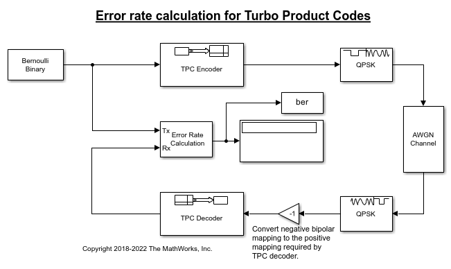
Several settings must be aligned with each other to synchronize encoding and decoding of the message. Start by deciding on a code rate, and aligning the TPC Encoder and TPC Decoder 2-D [N,K] pairs. For this example the default settings are used, [Nr,Kr] = [15,11] and [Nc,Kc] = [32,26].
The number of samples per frame and the sample time used by the Bernoulli Binary Generator block are determined based on the message length parameters, Number of rows in message, Kr and Number of columns in message, Kc.
Number of samples per frame = (Kr*Kc) = 286
Sample time = 1/(Kr*Kc) = 0.0035.
The white Gaussian noise the SNR setting is calculated based on the coding rate, modulation order, and Eb/N0.
Modulation order, M = 2
Eb/N0 = -11
rate = (Kr*Kc)/((Nr-Kr)*(Nc-Kc)) = 14.3
snr = 10*log10(M*rate*10^(ebn0/10)) = 3.5637
The noise variance used in the QPSK Demodulator Baseband block is calculated based on the SNR.
Noise variance = 1/10^(snr/10) = 1/10^(3.5637/10) = 0.4402
Run the model and observe the error rate calculation. Results will vary from run to run due to the use of random input data.
Bit error rate: 0.00042
Further Exploration
To run the model yourself, open the example using the button provided or by entering open slex_tpc_err_rate_calc at the MATLAB® command prompt. Consider modifying the model to change the signal to noise ratio. When adjusting TPC Encoder settings be sure to align settings in the TPC Decoder, Bernoulli Binary Generator, AWGN Channel, and QPSK Demodulator Baseband.
You can also select a web site from the following list:
Americas
- América Latina (Español)
- Canada (English)
- United States (English)
Europe
- Belgium (English)
- Denmark (English)
- Deutschland (Deutsch)
- España (Español)
- Finland (English)
- France (Français)
- Ireland (English)
- Italia (Italiano)
- Luxembourg (English)
- Netherlands (English)
- Norway (English)
- Österreich (Deutsch)
- Portugal (English)
- Sweden (English)
- Switzerland
- United Kingdom (English)